Operating instructions – Qmark CWH1000 Series - Small Room Fan-Forced Wall Heaters User Manual
Page 3
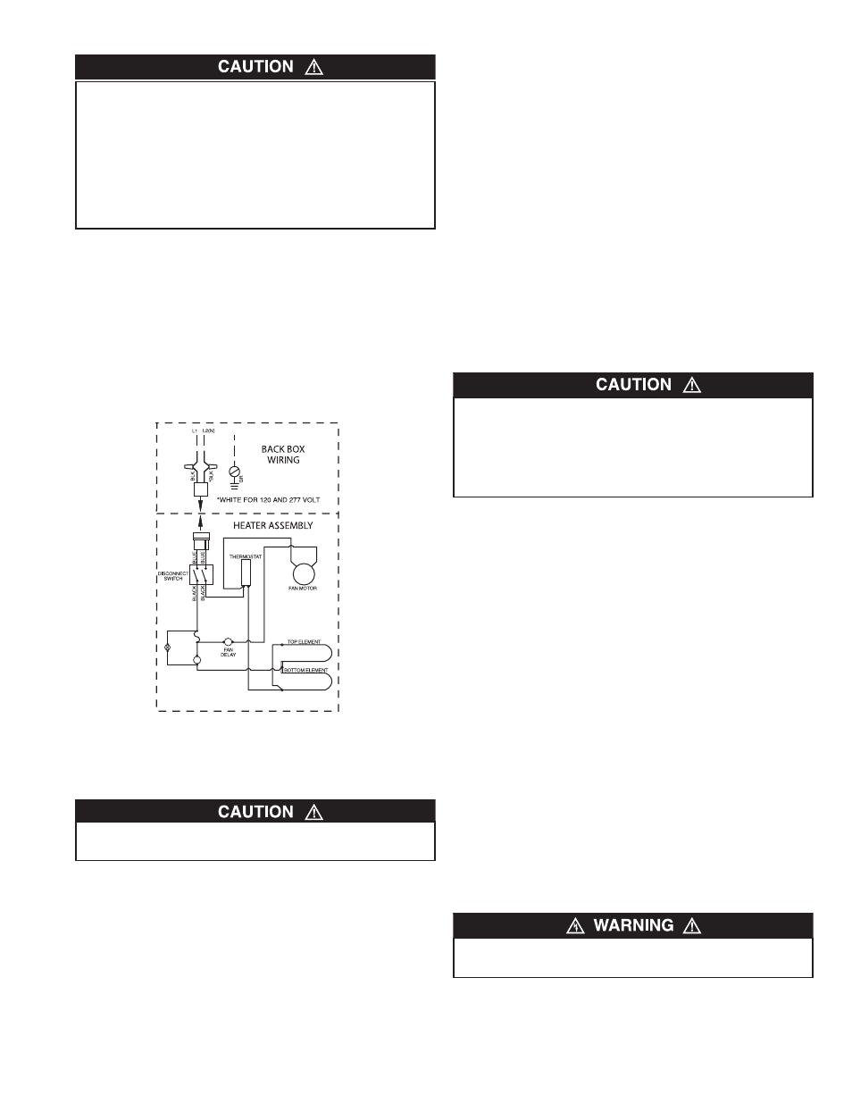
Installation and Wiring of Heater / Fan Assembly
1. Followingwiringdiagram,(Figure3)connectsupplywiringto
heaterleadwiresinbackbox.
NOTE: For120and277voltheatersconnectthewhiteneutral
supplyleadtotheheaterswhitepigtaillead,andconnectthe
blacksupplyleadtotheheaterblackpigtaillead.For208and
240voltheaterschangethecoloroftheheaterswhitepigtail
leadtoblackbywrappingwithblackelectricaltape(Most
electricalcodesrequirethesupplyleadstobeconnectedto
blackleads).Thenconnectthetwoblacksupplyleadstothe
twoblackreceptacleleads.
2. Securesupplygroundwireundergreengroundscrewin
backbox.
3. Insertwiringplugfromheater/fanassemblyintosocketin
backbox.
4. Fitheater/fanassemblyintobackboxandsecureinplace
with(2)screwsprovidedthroughthecenterslotsinthefan
assembly.
NOTE: Usethescrewsprovidedbythefactorytoinstallfan
decktothebackbox.
Installation of Grille and Thermostat Knob
1. Mountgrilletabsoverbrackets(top).
2. Insertscrewthroughbottomholeongrille.Screwthreads
intobackbox.
3. Fitthethermostatknobontothethermostatshaftandpush
intoplace.
OPERATING
INSTRUCTIONS
1. Heatermustbeproperlyinstalledbeforeoperation.
2. Afterheateriscompletelyassembled,rotatethermostatknob
counterclockwiseuntilcontrolstops.Thisistheminimum
heatsetting.
3. Turnpowersupplytoheater“ON”atmainswitchpanel.
4. Heatershouldnotoperate.Ifitoperatesdisconnectpower
andrecheckwiring.
5. Rotatethermostatclockwiseuntilitstops(maximumheat
setting).
6. Heaterandfanshouldcomeon.Ifheaterandfandonot
comeon,disconnectpowerandcheckwiring.
7. Allowheatertocontinuetooperateuntilroomtemperature
reachesdesiredcomfortlevel.Thenrotatethermostatknob
counterclockwiseslowlyuntilthermostatclicksoff.
8. Itmaybenecessarytoreadjustthermostatatimeorsountil
exactcomfortlevelisattained.Rotationintheclockwise
directionwillincreasetheamountoftimetheheaterwill
produceheat.Rotationinthecounterclockwisedirectionwill
reducetheamountoftimetheheaterison.
NOTE: Forbestresults,theheatershouldbeleft“ON”
constantlyduringtheheatingseasonasthethermostat,when
properlyset,willmaintainthedesiredtemperature.Inthefull
counter-clockwisepositiontheheaterwillremainoffuntilthe
roomtemperaturedropswellbelowfreezing.
How To Reset Over -Temperature Safety Control:
Thisheaterisprovidedwithanover-temperaturesafetycontrol
withabackupthermalfuse.Thesafetycontrolwillturnonared
warninglight,visiblethroughthefrontofthegrille,willilluminate
toalerttheownerthattheheaterisoffandrequiresattention.
Thiscontrol’sresetbuttonislocatedbehindthegrillejustabove
theredwarninglight.Theresetbuttoncanbeseenthroughthe
frontgrillewhentheheaterisinstalled.Toreset,allowtheheater
tocool,thenusinganobjectthatwillfitthroughthelouvers
(suchasasmallflatheadscrewdriver),pushtheresetbutton
thatisvisibleinthefanpanel.Theheatershouldimmediately
returntonormaloperation.Ifthealarmlightremainsonafterthe
heaterhascooledandthemanual-resetbuttonhasbeen
pressed,thethermalfusemayhaveactivated.Ifthisoccurs,the
heatermustbecheckandrepairedbyaqualifiedelectrician.
DO NOT USE A REMOTE THERMOSTAT WITH THIS
HEATER. BUILT IN THERMOSTAT CYCLES THE HEATING
ELEMENT ONLY. FAN DELAY CONTROL AUTOMATICALLY
TURNS FAN ON AND OFF, AND PROVIDES A FAN DELAY
OFF FEATURE TO REMOVE RESIDUAL HEAT AFTER
THERMOSTAT HAS TURNED HEATING ELEMENTS OFF.
WIRING OF HEATER IN ANY MANNER WHICH DEFEATS
THE FAN DELAY OFF FEATURE CAN RESULT IN
OVERHEATING AND PERMANENT DAMAGE TO HEATER,
ANDWILLVOIDTHEWARRANTY.
BESUREALLWIRINGISSECURELYROUTEDAWAYFROM
FANANDELEMENT.
IFFANSHUTSOFFIMMEDIATELY,THERMOSTATWIRINGIS
INCORRECTANDMUSTBECHANGED.FANMUSTDELAY
SHUTTINGOFFTOEXPELRESIDUALHEATTOPREVENT
PREMATURE
AGING
OF
INTERNAL
HEATER
COMPONENTS THAT COULD LEAD TO A HAzARD OR
PREMATUREFAILURE.
DO NOT TAMPER WITH OR BYPASS ANY SAFETY
CONTROLLIMITSINSIDEHEATER.
3
ALARM
LIGHT
THERMAL
FUSE
MANUAL
RESET
LIMIT
ALARM
LIGHT
THERMAL
FUSE
MANUAL
RESET
LIMIT
Figure 3