B.3 single mode and multimode fiber optic cabling – Cabletron Systems STHI User Manual
Page 77
Single Mode and Multimode Fiber Optic Cabling
Page B-5
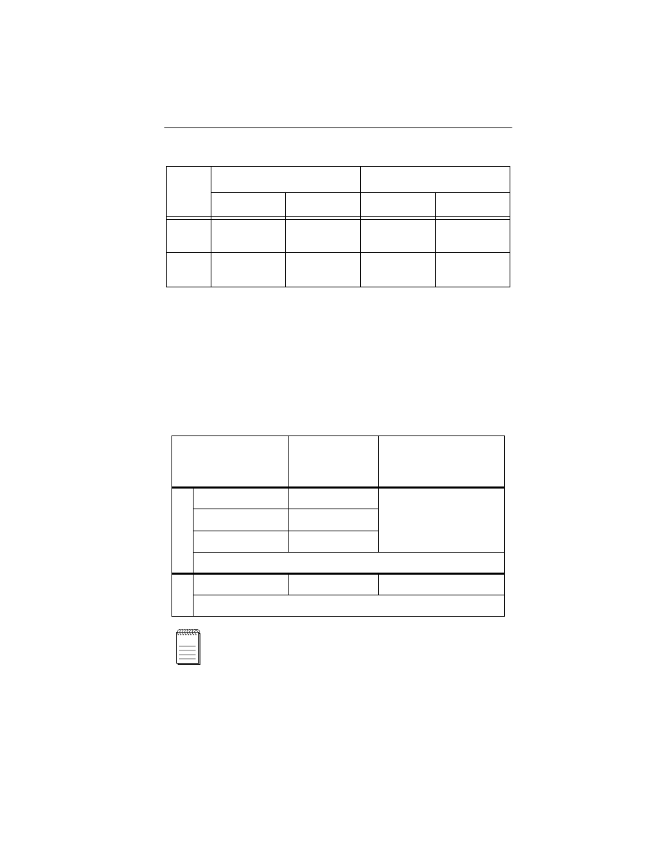
B.3 Single Mode and Multimode Fiber Optic Cabling
TPIM models F2 and F3 support multimode and singlemode fiber optic
cable respectively. Table B-5 below defines total signal attenuation
tolerances for fiber cabling. Both media have a typical constant attenuation
rate per km of fiber cable and each connector on the cable system
contributes significant additional attenuation. Maximum drive distances
define maximum allowable cable length.
The attenuation values shown in Table B-5 include the
attenuation attributable to cables, connectors, patch panels,
and reflection losses due to impedance mismatches in the
segment.
Table B-4. STP Maximum Lengths
IBM
Type
Max. Lobe Length
Max. Drive Distance
4 Mbps
16 Mbps
4 Mbps
16 Mbps
1 & 2
200 meters
(660 feet)
100 meters
(300 feet)
770 meters
(2525 feet)
346 meters
(1138 feet)
6 & 9
30 meters
(99 feet)
30 meters
(99 feet)
513 meters
(1683 feet)
230 meters
(755 feet)
Table B-5. Signal Tolerances for Fiber Optic Cable
Cable Type
Total
Allowable
Attenuation
Maximum
Drive Distance
Multimode
50/125
µ
m
13.0 dB or less
2 km (2187.2 yards)
62.5/125
µ
m
16.0 dB or less
100/140
µ
m
19.0 dB or less
Typical Signal Attenuation Rate:
≤
2.5 dB/km.
Single
8/125-12/125
µ
m
10.0 dB or less
10 km (10936.0 yards).
Typical Signal Attenuation Rate:
≤
0.5 dB/km.
NOTE