Dell PowerEdge 7250 User Manual
Page 33
SR870BN4 Error Reference Guide
POST Codes
Revision 1.0
27
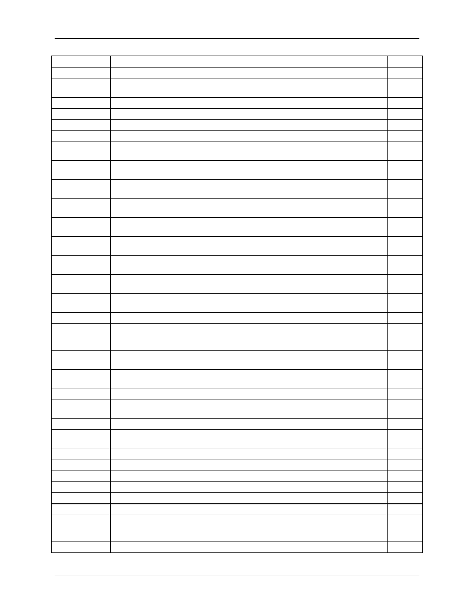
Code Value
Module
Display
after the video ROM had control.
0x002E
Complete post-video ROM test processing. If the EGA/VGA controller is not found,
perform the display memory read/write test next.
South
0x0037
The display mode is set. Display the power on message next.
South
0x0038
Initialize the bus input, IPL, and general devices next, if present.
South
0x0039
Late processor self test. Display bus initialization error messages.
South
0x003A
The new cursor position has been read and saved. Displaying the Hit F2 message.
South
0x0053
The memory size information and the CPU registers are saved. Entering real mode.
South
0x0054
Shutdown was successful. The CPU is in real mode. Disabling the Gate A20 line, and
parity next.
South
0x0057
The A20 address line, parity disabled. Adjusting the memory size depending on
relocation and shadowing next.
South
0x0058
The memory size was adjusted for relocation and shadowing. Clearing the Hit F2
message.
South
0x0059
The Hit F2 message is cleared. Starting the DMA and interrupt controller test next.
South
0x0060
The DMA page register test passed. Performing the DMA Controller 1 base register
test next.
South
0x0062
The DMA controller 1 base register test passed. Performing the DMA controller 2 base
register test next.
South
0x0065
The DMA controller 2 base register test passed. Programming DMA controllers 1 and 2
next.
South
0x0066
Completed programming DMA controllers 1 and 2. Initializing the 8259 interrupt
controller next.
South
0x007F TBD.
South
0x0080
Mouse initialization of PS/2 mouse to program the IRQ level to edge triggered or level
triggered. The keyboard test has started. Clearing the output buffer and checking for
stuck keys. Issuing the keyboard reset command next.
South
0x0082
The keyboard controller interface test completed. Write the command byte and
initializing the circular buffer next.
South
0x0083
The command byte was written and global data initialization has completed. Checking
for a locked key next.
South
0x0084
Locked key checking is over. Identify ATAPI devices.
South
0x0089
The programming after Setup has completed. Displaying the power on screen
message next.
South
0x008B
Init boot devices. Check for and reset mouse.
South
0x008C
Npost adjustments to setup. Form E820 tables. Program SETUP-selected chipset and
Sup-IO parameters.
South
0x008D
The Setup options are programmed. Resetting the hard disk controller.
South
0x008E
OEM patches executed. Decompress INT13 module and init ATA & ATAPI devices.
South
0x0093
Done with ATA and ATAPI init. Set printer, RS-232 time out.
South
0x0095
Initializing the bus option ROMs from C800 next. SCSI opt ROM init.
South
0x0091
Configuring the hard disk drive controller. Initializing the CD ROM drive.
South
0x0092
TBD.
South
0x0098
The adaptor ROM had control and has now returned control to BIOS POST.
Performing any required processing after the option ROM returned control. Restoring
INT10 vector.
South
0x0008
Debugging code.
South