Dell Precision T7400 (Late 2007) User Manual
Page 184
184
Adding and Replacing Parts
NOTE:
Align the memory module carefully to ensure that it is facing the correct
direction; FBDs on memory riser cards 1 and 2 face a different direction than those
on riser cards 3 and 4.
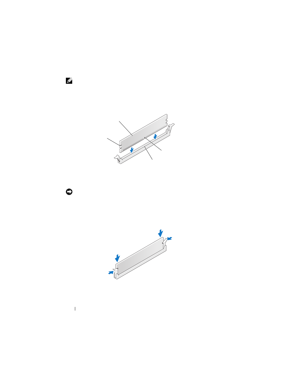
9 Align the notch on the bottom of the module with the crossbar in the
connector.
NOTICE:
To avoid damage to the memory module, press the module straight down
into the connector while you apply equal force to each end of the module.
10 Insert the module into the connector until the module snaps into position.
If you insert the module correctly, the securing clips snap into the cutouts
at each end of the module.
1 cutouts (2)
2 memory module
3 notch
4 crossbar
3
2
1
4
See also other documents in the category Dell Computers:
- Inspiron 530 (2 pages)
- OptiPlex 755 (45 pages)
- OptiPlex 755 (248 pages)
- OptiPlex 755 (622 pages)
- OptiPlex 755 (528 pages)
- OptiPlex 755 (82 pages)
- OptiPlex 760 (76 pages)
- OptiPlex 760 (203 pages)
- OptiPlex 745 (212 pages)
- OptiPlex 745 (360 pages)
- OptiPlex 745 (428 pages)
- OptiPlex 780 (10 pages)
- OptiPlex 780 (74 pages)
- OptiPlex 780 (80 pages)
- OptiPlex 780 (73 pages)
- OptiPlex 780 (40 pages)
- OptiPlex 780 (14 pages)
- OptiPlex 780 (89 pages)
- OptiPlex GX620 (221 pages)
- OptiPlex GX620 (294 pages)
- OptiPlex GX620 (338 pages)
- Inspiron 530 (226 pages)
- OptiPlex 960 (Late 2008) (16 pages)
- OptiPlex GX260 (100 pages)
- OptiPlex GX260 (235 pages)
- OptiPlex FX160 (Late 2008) (132 pages)
- OptiPlex FX160 (20 pages)
- OptiPlex FX160 (Late 2008) (20 pages)
- OptiPlex 210L (150 pages)
- OptiPlex 210L (130 pages)
- OptiPlex 210L (128 pages)
- OptiPlex 210L (300 pages)
- OptiPlex 210L (258 pages)
- OptiPlex 320 (132 pages)
- OptiPlex 320 (312 pages)
- OptiPlex 320 (266 pages)
- OptiPlex 320 (356 pages)
- OptiPlex 320 (44 pages)
- OptiPlex 320 (140 pages)
- OptiPlex GX240 (283 pages)
- OptiPlex GX240 (298 pages)
- OptiPlex GX240 (182 pages)
- OptiPlex GX240 (144 pages)
- OptiPlex GX240 (121 pages)
- OptiPlex GX240 (86 pages)