Operators instructions combipress™, type pfmx, Combiview, Dfon display – Baumer CombiPress PFMH User Manual
Page 5: Electrical connection
www.baumer.com
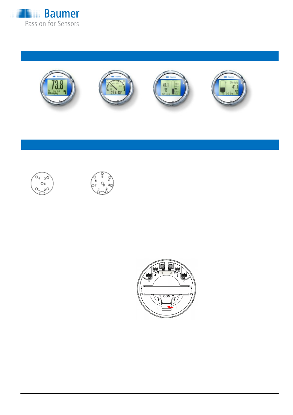
CombiView
™
DFON display
There are 9 different display modes available
Digital
Analogue
Bar graph
Tank
small
analogue
horizontal
tank illustration
large
same w. bar graph
vertical
bottle illustration
same w. value
Electrical connection
Pin 1
+ 4…20 mA (not connected)
Pin 2
- 4…20 mA (not connected)
Pin 3
Relay 1
Pin 4
Relay 1
Pin 5
Relay 2
Pin 6
Relay 2
Com 1
FlexProgrammer
① red
Com 2
FlexProgrammer
② black
The PFMx with DFON display is delivered with terminal 1 and 2 not connected. The DFON is powered and will have data direct
through a special ribbon cable (UnitCom). Via UnitCom the DFON and PFMx transmitter can be programmed together when con-
necting the FlexProgrammer to Com 1 and COM 2 on the back of the display.
Pin 3 and 5 can be jumpered together if common supply is used for the two relays, e.g. via a M12 5-pin connector. Two galvanic
separated relay outputs will require a 8-pin M12 connector if plug connection is required. If cable glands is used the terminals 4...6
is connected via the screw terminals.
Electrical connection
Operators instructions
CombiPress™, type PFMx
UnitCom
Operators instructions: 11120948 PFMx Page 5 / 12
Electrical connection
M12, 5-wire
M12, 8-wire
1 + supply, 4...20 mA
1 n.c.
2 Common for relays
2 + supply, 4...20 mA
3 - supply, 4...20 mA
3 Relay 1
4 Relay 1
4 Relay 1
5 Relay 2
5 Relay 2
6 Relay 2
7 - supply, 4...20 mA
8 n.c.
Cable gland
Transmitter
-
- supply, 4...20 mA
+
+ supply, 4...20 mA
Com 1 Red clip (FlexProgrammer)
Com 2 Black clip (FlexProgrammer)
Display
1
n.c.
2
n.c.
3
Relay 1
4
Relay 1
5
Relay 2
6
Relay 2
Com 1 Red clip (FlexProgrammer)
Com 2 Black clip (FlexProgrammer)