Kyle, Initializing the control, Ac reclosers – Cooper Lighting S280-79-10 User Manual
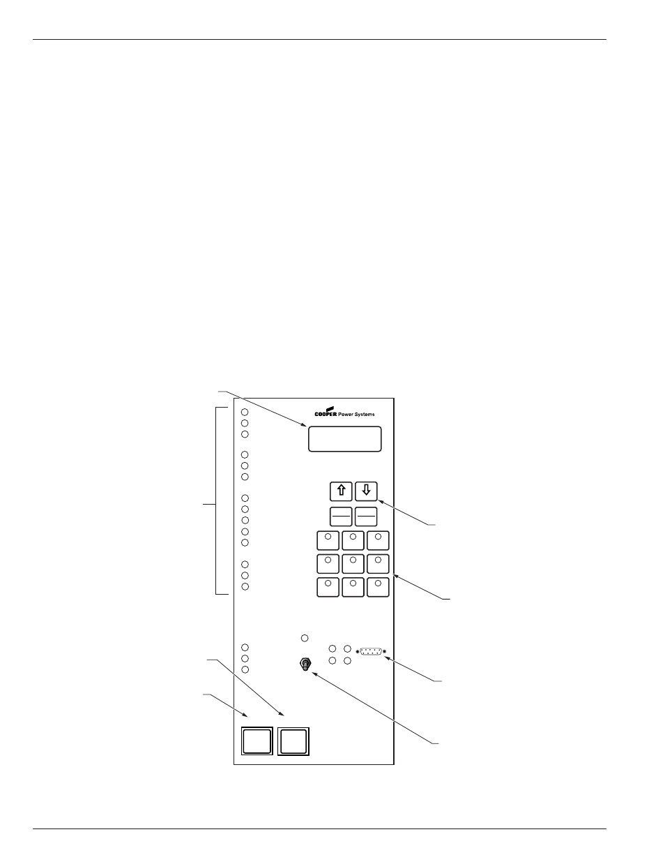
Page 4: Operation upon loss of ac power, Figure 2, Form 5 recloser control operator panel
AC Reclosers
Power to operate the tripping and closing solenoids in the
recloser is provided by the power capacitor located
behind the operator panel of the control. A sealed, 24-volt,
lead acid battery is located in the lower portion of the con-
trol cabinet and is utilized to provide operating and trip-
ping energy when AC power is temporarily lost. The
control is equipped with an ac-powered, temperature-
compensated battery charger.
Operation Upon Loss Of AC Power
If the control is equipped with the standard 24 Vdc lead-
acid battery, the control maintains full operation from the
battery power supply for a minimum of 32 hours at 20°C
(24 hours at -40°C). To prevent battery damage, the con-
trol shuts down automatically upon detection of low bat-
tery voltage below 22.7 Vdc.
Control programming settings and parameters—including
event recorder, duty monitor, and data profile metering
parameters—are stored in non-volatile memory and
retained upon loss of control power. The time/date clock
resets to 0:00:00, 1970 upon loss of control power.
The AC power LED indicator on the operator panel of the
control will turn off after 15 seconds upon loss of AC
power. The indicator will illuminate immediately upon
return of ac power.
Initializing the Control
Two methods are available to initialize the Form 5 control.
Method 1: Connect AC power to the input connector ter-
minal TB-1. Refer to the Customer Connec-
tions for AC Power section of this manual.
Method 2: Connect the battery terminal on the control
and press the MANUAL BATTERY RECON-
NECT button located on the Form 5 power
supply. See Figure 4.
Note:
Method 2 powers the control off the battery
and is not intended for long term operation.
In both methods, after initialization, set the control clock
via the interface software.
Kyle Form 5, Form 5 UDP, Form 5 DC NOVA Recloser Control Installation and Operation Instructions
4
CONTROL OK
AC POWER
ABOVE MIN TRIP
REVERSE POWER FLOW
RECLOSER MALFUNCTION
CHECK BATTERY
BUSHINGS 1-2 FAULT TARGET
BUSHINGS 3-4 FAULT TARGET
BUSHINGS 5-6 FAULT TARGET
GROUND FAULT TARGET
SENSITIVE-GROUND FAULT TARGET
BUSHINGS 1-2 VOLTAGE
BUSHINGS 3-4 VOLTAGE
BUSHINGS 5-6 VOLTAGE
RECLOSER CLOSED
RECLOSER OPEN
CONTROL LOCKOUT
BACK
NEXT
LAMP
TEST
CHANGE
RESET
TARGETS
RESET
MAX CURRENT
GND TRIP
BLOCKED
NON
RECLOSING
SUPERVISORY
BLOCKED
COLD LOAD
PICK UP
BLOCKED
BATTERY
TEST
FAST
TRIPS
DISABLED
ALTERNATE
PROFILE
NO. 1
ALTERNATE
PROFILE
NO. 2
ALTERNATE
PROFILE
NO. 3
HOT LINE
TAG
ON
OFF
TX 3
RX 3
CLOSE
TRIP
(LOCKOUT)
KYLE
®
FORM 5
RECLOSER CONTROL
RS232
TX 2
RX 2
LED Indicators
LCD Display
TRIP (LOCKOUT)
Pushbutton
CLOSE Pushbutton
LCD Display Dedicated
Function Keys
Operation "Hot Keys"
RS232 Data Port
Hot Line Tag
Figure 2.
99005KM
Form 5 recloser control operator panel.