Mounting the control – Cooper Lighting S280-79-10 User Manual
Page 33
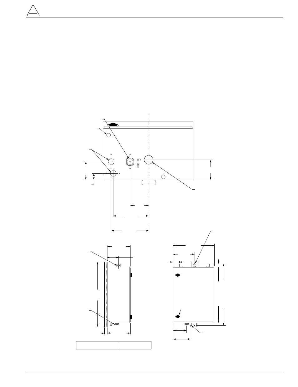
Mounting the Control
Mount the Form 5 recloser control in a convenient, acces-
sible location. Mounting dimensions are provided in Fig-
ure 28.
• For pole-mounted installation, a hole and keyway in
the control mounting bracket accommodates a 5/8”
bolt.
• For substation installation, brackets are available as
an accessory for mounting the control to a substation
frame.
Limits on control cable length are determined by the max-
imum distance between the control and recloser:
• Up to 410 m (125* ft) for solenoid-operated reclosers
(VWE, VWVE27, VWVE38X, WE, WVE27, WVE38X,
and NOVA).
• Up to 10,7 m (35* ft) for motor-operated reclosers
(VSA12, VSA12B, VSA16, VSA20, VSA20A, VSO12,
VSO16).
Up to 41 m (135* ft) for NOVA DC.
* These lengths are based on standard control cables.
Consult your Cooper Power Systems representative if
longer cable lengths are required.
S280-79-10
33
!
SAFETY
FOR LIFE
CONTROL WEIGHT
52 kg (115 LBS)
350mm
(13-13/16")
30mm
(1-1/8")
Male Receptacle
For Control Cable
685mm
(27")
Grounding Terminal
One Internal and
One External
Use No. 14 To No. 4
Stranded Wire
110mm
(4-3/8")
165mm
(6-1/2")
580mm (23")
640mm (25-1/4")
40mm (1-1/2")
380mm
(15")
30mm (1-1/8") Hole
In Lifting Lug
240mm
(9-1/2")
76mm
(3")
480mm
(19")
Mtg Hole For
15mm (5/8") Max
Bolt Dia.*
Die-cast-zinc latchable
Handle For User-
Provided Utility-Grade
Padlock
130mm
(5-1/8")
190mm
(7-3/8")
120mm (4-3/4")
45mm (1-3/4") Dia. Hole
For Automation Accessory
(Cap-Plug Installed)
Vent
Female Receptacle
For Control
Cable
* USER-PROVIDED HARDWARE
CL
CL
110mm
(4-1/4")
40mm
(1-1/2")
200mm
(7-7/8")
35mm (1-7/16") Dia. Hole
For User 120Vac
Input Connection
(Cap-Plug Installed)
160mm
(6-3/8")
Figure 28.
Control cabinet mounting dimensions.