Cooper Lighting S280-79-10 User Manual
Page 35
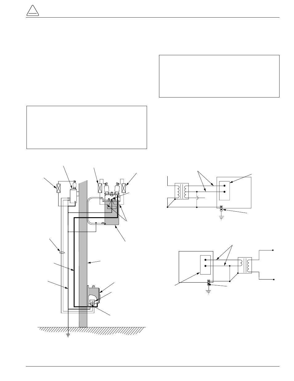
Installation of a Form 5 control with a local supply voltage
transformer must include the following:
• Protection of the recloser bushings and the supplying
transformer with lightning arresters.
• Grounding of the recloser head and tank.
• Grounding of the transformer tank.
• Grounding of the control cabinet.
• Grounding of the SCADA equipment.
4-Wire Multi-Grounded Systems
3-Wire Ungrounded and Impedance Grounded Systems
The use of a grounding mat may be required depending
upon the local safety regulations defining the permissible
step and touch potential levels. Consult local regulations
for proper grounding procedures.
S280-79-10
35
!
SAFETY
FOR LIFE
Surge
Arrester
Recloser
Head Ground
Surge
Arrester
Transformer
Surge
Arrester
Arrester Ground
Recloser
Pole
Supply
Voltage
Pole
Ground
Form 5 LS
Control
Customer Ground Connection
At External Lug
NEU
AC
GND
NEU
AC
Input
Terminal
Block
Control
Cable
AC
NEUTRAL
Form 5 LS Control
Supply Voltage
Transformer
ELECTRICAL CONNECTIONS
Line to Neutral connected transformer
Form 5 LS Control
AC
NEUTRAL
Input Terminal
Block
Supply Voltage
Transformer
ELECTRICAL CONNECTIONS
Line to Line connected transformer
Line
to
Line
Voltage
External
Ground Lug
Input Terminal
Block
External
Ground Lug
Figure 29.
Recommended grounding method for the Form 5 Control installed on 4-wire multi-grounded, 3-wire
ungrounded, or impedance-grounded systems with local supply voltage transformer.
IMPORTANT: In pole-mounted applications, a
ground connection must be made between the
recloser, transformer, recloser control, and SCADA
equipment for proper protection of the equipment. The
pole ground must be sized per local utility practices to
minimize the impedance between the recloser and the
control.
IMPORTANT: All external inputs to the Form 5 con-
trol must be routed within 8 inches of their correspond-
ing ground. During a surge, a potential of approximately
1.5 kV per foot can develop in the conductors. Differ-
ences between conductor and ground path lengths can
add additional stress to the control components in the
event of a power surge.
Grounding with a Local Supply Voltage Transformer; 4-Wire Multi-Grounded,
3-Wire Ungrounded, or Impedance-Grounded