Optical drive, Removing an optical drive – Dell OptiPlex 745 User Manual
Page 41
Most interface connectors are keyed for correct insertion; that is, a notch or a missing pin on one connector matches a tab or a filled-in hole on the other
connector. Keyed connectors ensure that the pin-1 wire in the cable (indicated by the colored stripe along one edge of certain cables—SATA cables do not use
a colored stripe) goes to the pin-1 end of the connector. The pin-1 end of a connector on a board or a card is usually indicated by a silk-screened "1" printed
directly on the board or card.
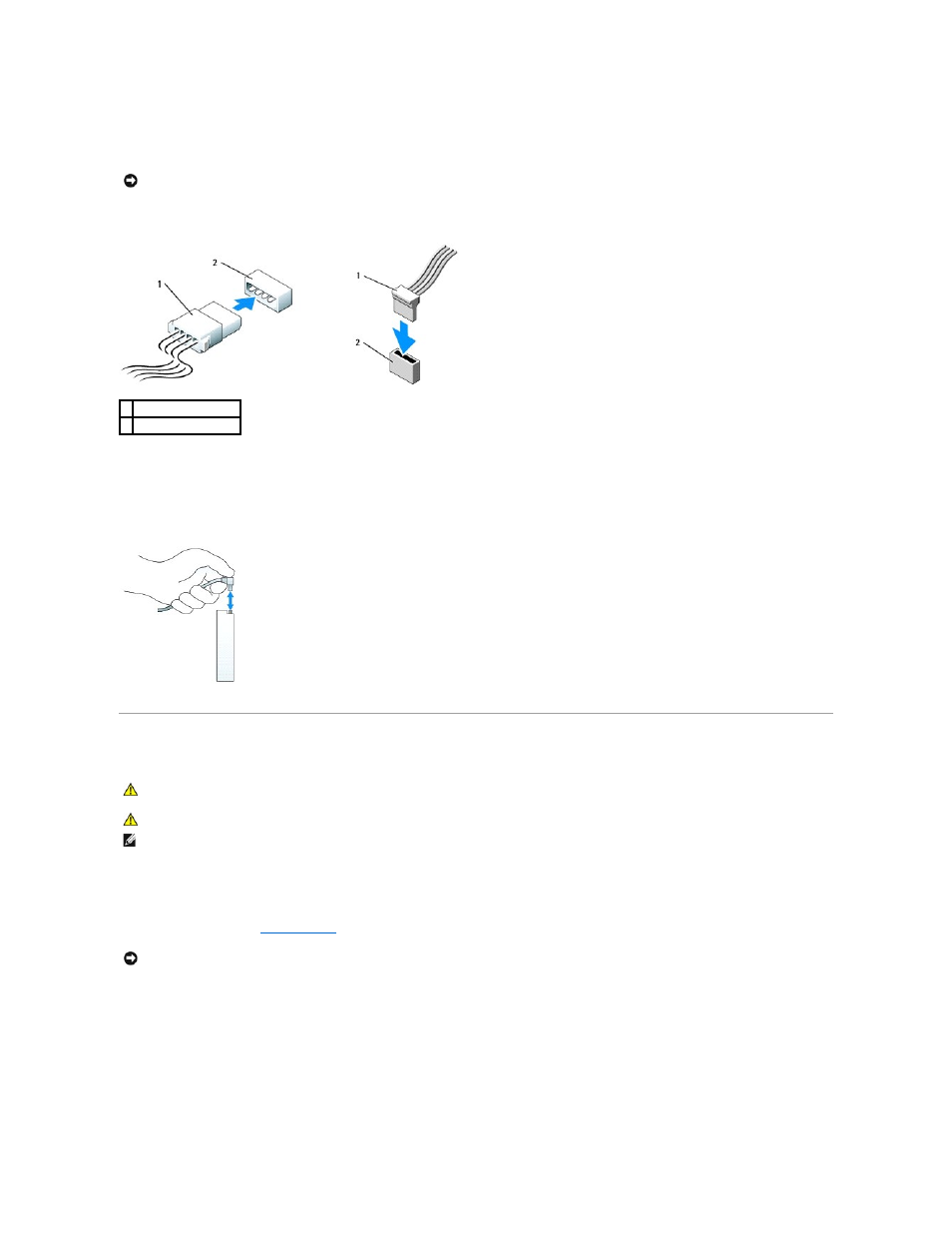
Power Cable Connectors
Connecting and Disconnecting Drive Cables
When removing a cable with a pull-tab, grasp the colored pull-tab and pull until the connector detaches.
When connecting and disconnecting a SATA data cable, hold the cable by the black connector at each end.
Optical Drive
Removing an Optical Drive
1.
Follow the procedures in
Before You Begin
.
2.
Pull up on the drive-release latch and slide the drive towards the back of the computer. Then, lift up to remove the drive from the computer.
NOTICE:
Inserting a cable incorrectly prevents the drive from operating and could damage the controller, the drive, or both.
1 power cable
2 power input connector
CAUTION:
Before you begin any of the procedures in this section, follow the safety instructions in the Product Information Guide.
CAUTION:
To guard against electrical shock, always unplug your computer from the electrical outlet before removing the computer cover.
NOTE:
If you will be operating your computer without an optical drive or a 3.5-inch device (floppy drive or Media Card Reader) installed, the appropriate
drive-bay insert must be installed in place of the drive. Contact Dell if you need a drive-bay insert.
NOTICE:
Do not pull the drive out of the computer by the drive cables. Doing so may cause damage to cables and the cable connectors.