Drives, General installation guidelines – Dell OptiPlex 745 User Manual
Page 202
Back to Contents Page
Drives
Dell™ OptiPlex™ 745 User's Guide
Your computer supports:
l
One SATA (serial ATA) hard drive
l
One optional D-module optical drive, second hard drive, or floppy drive in the module bay
General Installation Guidelines
A SATA hard drive should be connected to the connector labeled "SATA0" on the system board (see
System Board Components
).
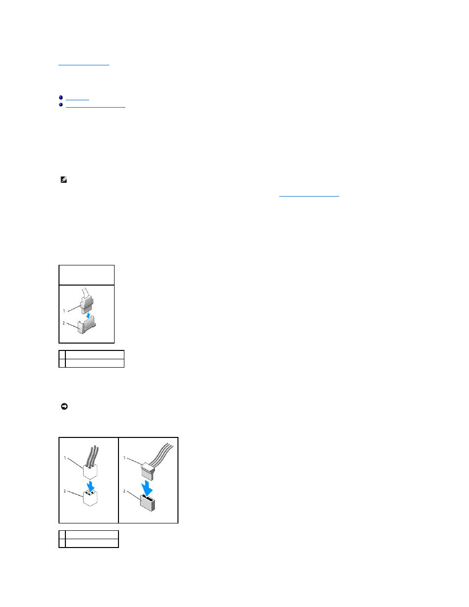
Connecting Drive Cables
When you install a drive, you connect two cables—a DC power cable and a data cable—to the back of the drive.
Drive Interface Connectors
Most interface connectors are keyed for correct insertion; that is, a notch or a missing pin on one connector matches a tab or a filled-in hole on the other
connector. Keyed connectors ensure that the pin-1 wire in the cable (indicated by the colored stripe along one edge of certain cables—SATA cables do not use
a colored stripe) goes to the pin-1 end of the connector. The pin-1 end of a connector on a board or a card is usually indicated by a silk-screened "1" printed
directly on the board or card.
Power Cable Connectors
NOTE:
For information on installing D-module drives, see the documentation that came with your optional device.
SATA Connector
1 interface cable connector
2 interface connector
NOTICE:
Inserting a cable incorrectly prevents the drive from operating and could damage the controller, the drive, or both.
1 power cable
2 power input connector