Side view, Back view, Back-panel connectors – Dell OptiPlex 745 User Manual
Page 188
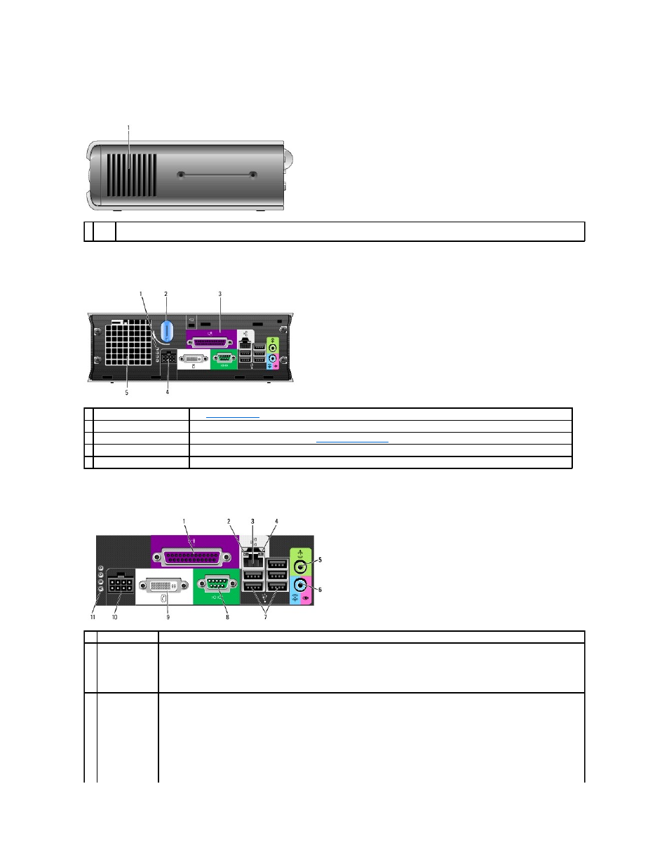
Side View
Back View
Back-Panel Connectors
1 vents
The vents located on each side of the computer help prevent your computer from overheating. To ensure proper ventilation, do not block these
cooling vents.
1 diagnostic lights
See
Diagnostic Lights
for a description of light codes that can help you troubleshoot problems with your computer.
2 computer cover release knob Rotate this knob in a clockwise direction to remove the cover.
3 back-panel connectors
The connectors for your computer (see
4 power connector
Insert the power cable.
5 vents
The vents help prevent your computer from overheating. To ensure proper ventilation, do not block these cooling vents.
1
parallel connector Connect a parallel device, such as a printer, to the parallel connector. If you have a USB printer, plug it into a USB connector.
2
link integrity light
l
Green — A good connection exists between a 10-Mbps network and the computer.
l
Orange — A good connection exists between a 100-Mbps network and the computer.
l
Yellow — A good connection exists between a 1000-Mbps (1-Gbps) network and the computer.
l
Off — The computer is not detecting a physical connection to the network or the network controller is turned off in system
setup.
3
network adapter
To attach your computer to a network or broadband device, connect one end of a network cable to either a network jack or your
network or broadband device. Connect the other end of the network cable to the network adapter connector on the back panel of
your computer. A click indicates that the network cable has been securely attached.
NOTE:
Do not plug a telephone cable into the network connector.
On computers with a network connector card, use the connector on the card.
It is recommended that you use Category 5 wiring and connectors for your network. If you must use Category 3 wiring, force the