Dell OptiPlex 745 User Manual
Page 209
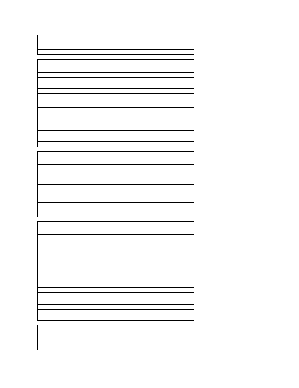
Drives
Externally accessible
one D-module bay for an optical drive, second hard
drive, or floppy drive
Internally accessible
one bay for a 1-inch-high hard drive
Connectors
External connectors:
Serial
9-pin connector; 16550C-compatible
Parallel
25-hole connector (bidirectional)
Video
28-hole DVI connector
Network adapter
RJ45 connector
USB
two front-panel and five back-panel USB 2.0–
compliant connectors
Audio
two back-panel connectors for line-in/ microphone
and line-out; two front-panel connectors for
headphones and microphone
D-Dock
standard D-dock connector for devices such as D-
Dock advanced port replicators and expansion
stations.
System board connectors:
SATA
7-pin connector
Fan
one 3-pin and two 5-pin connectors
Key Combinations
in Microsoft® Windows® XP, brings up the Windows
Security window; in MS-DOS® mode, restarts
(reboots) the computer
starts embedded system setup (during system start-
up only)
automatically starts the computer from the network
environment specified by the remote boot
environment (PXE) rather than from one of the
devices in the system setup Boot Sequence option
(during start-up only)
displays a boot device menu that allows the user to
enter a device for a single boot (during system start-
up only) as well as options to run hard-drive and
system diagnostics
Controls and Lights
Power control
push button
Power light
green light — Blinking green indicates a sleep mode;
solid green indicates the power-on state.
amber light — Blinking amber indicates a problem
with an installed device; solid amber indicates an
internal power problem (see
Power Problems
).
Power supply status light
green light — Solid green indicates the power
adapter is connected to an AC outlet and the
computer.
amber light — Solid amber indicates the power
adapter is connected to an AC outlet but not the
computer.
Hard-drive access light
green
Link integrity light (on integrated network adapter)
green light for 10-Mb operation; orange light for 100-
Mb operation; yellow light for a 1000-Mb (1-Gb)
operation
Activity light (on integrated network adapter)
yellow blinking light
Diagnostic lights
four lights on the back panel. See
Diagnostic Lights
.
Standby power light
AUX_PWR on the system board
Power
DC external power supply:
NOTE:
Power consumption can be zero when the