Cooper Instruments & Systems DFI 1650 Multi-Channel Digital Force Indicator User Manual
Page 11
CF 126
8
Nov 2001
Model DFI
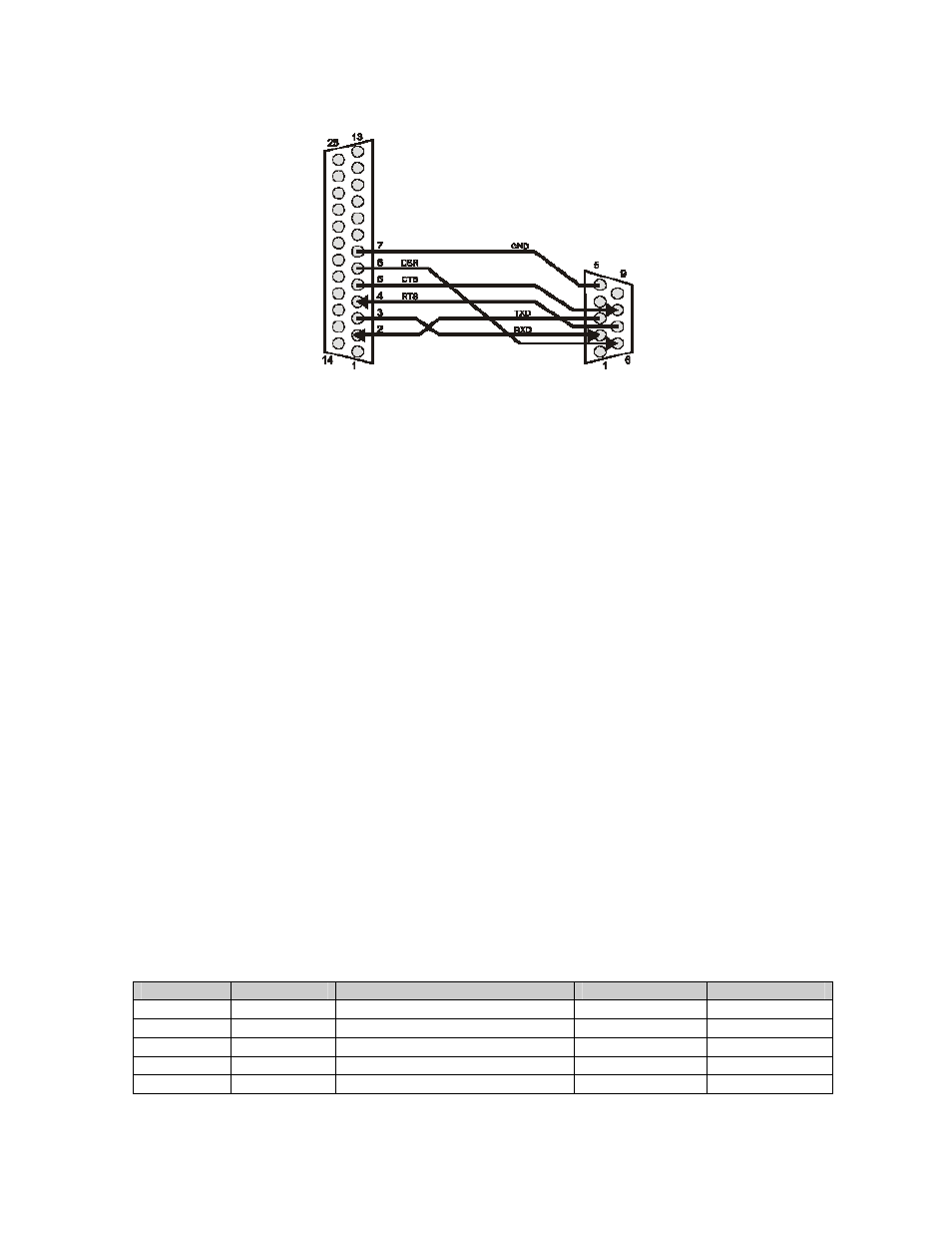
Computer or Terminal
DB-25
connector
DB-9
connector
DCE
DTE
Figure 4-2: Wiring to 9-pin DTE
Chapter 5 RS422/RS-485 Installation Notes
5.1 Introduction
This chapter provides wiring examples and hardware information for RS-422/RS-485 communications.
"Bus master" will be used to refer to the personal computer, programmable controller, terminal, data
acquisition system, etc. to which the instrument is connected.
5.2 Installation Overview
Every slave instrument on the communications bus must have a unique 2-character address. Before
wiring multiple instruments into an RS-422/RS-485 communications bus, it is recommended that you read
this document thoroughly and then follow the sequence given below to avoid problems during installation.
1. Determine if the bus master has an RS-422 interface or a RS-485 interface. Wire up one, and
only one, slave instrument to the communications loop z according to the wiring diagrams in this
chapter.
2. Determine the address used by this DFI instrument (factory default is "00") by using the front
panel setup menus. This procedure is explained in (I) "Addressing". Use this address to establish
communications with this instrument.
3. Change this instrument's address to another unique value, such as "01 ", using the "W4"
command as explained in "Addressing".
4. Wire the next instrument to the communications loop and repeat steps 2-4 until the last unit is on-
line.
5.3 System Connector Pinout
The table below lists the pins on the System Connector used for RS-422/RS-485 communication. Other
pins on the System Connector may be used for other purposes.
Table 5-1: System Connector Pins used for RS-422/RS-485
Pin
Name
Function
Input/Output
Reference Pin
7 GND
RS-422/RS-485
reference
Reference -
12
(-) TX
RS-485 Transmit -
Output
7
13
(+) TX
RS-485 Transmit +
Output
7
24
(-) RX
RS-485 Receive -
Input
7
25
(+) RX
RS-485 Receive +
Input
7