Cooper Instruments & Systems DFI 250X Digital Weight Indicator User Manual
Page 8
CF 147
4
version 1.1
The DC supply need not be regulated, provided that it is free of excessive electrical noise and sudden transients.
The instrument can be operated from a high quality AC wall transformer as long as there is sufficient capacity to
drive both it and the load cells.
3.8 Load Cell Connection
3.8.1 Load Cell Signals and Scale Build
Very low output scale bases may be used but may induce some instability in the weight readings when used with
higher resolutions. Generally speaking, the higher the output, or the lower the number of divisions, the greater the
display stability and accuracy.
The instrument can display the milliVolt-per-Volt reading that can be used to check scale base signal output levels.
For more information, refer to SCALE (Scale Base Test Display) section 7.4.8.
The instrument may be connected for either 4-wire or 6–wire operation. To correspond with the actual cabling
installation the instrument must be configured in setup to the correct setting. For more information, refer to CABLE
(4-Wire or 6-Wire)
section 7.4.1.
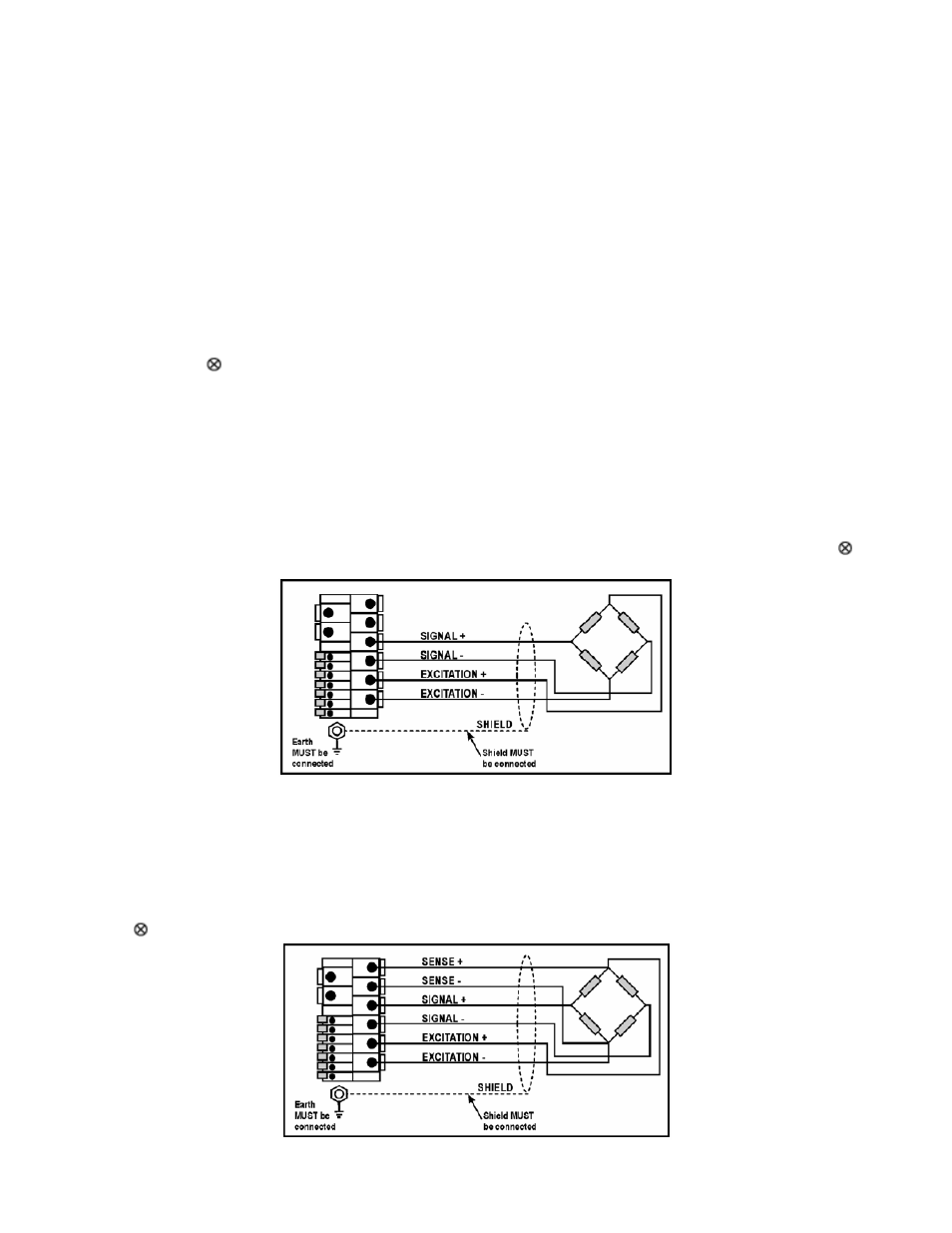
3.8.2 4-Wire Connection
The minimum connectivity requirements are the connection of four wires (i.e. Excitation + and – along with Signal +
and –). Internally the instrument has a precision analog switch that can be used to connect the Sense + and – lines
directly to the Excitation + and – lines.
Any addition to the load cell manufacturer's cable length using 4-wire connection is only recommended for short
cable runs. Where long additions to cable lengths are needed, a 6-wire extension is required.
The BUILD: CABLE option must be set to 4 to allow for 4-wire connection. Refer to CABLE (4-Wire or 6- Wire)
section 7.4.1.
Figure 3: 4-Wire Connections
3.8.3 6-Wire Connection
The excitation and signal lines are connected the same as for a 4-wire installation. The extra two wires (Sense +
and –) should be connected to the Excitation + and – lines as close as possible to the load cell itself. Typically
these connections are made in a load cell termination box.
The BUILD: CABLE option must be set to 6 (the default) to allow for 6-wire connection. Refer to CABLE (4- Wire or
6-Wire)
section 7.4.1.