0 data entry – Cooper Instruments & Systems DFI 250X Digital Weight Indicator User Manual
Page 12
CF 147
8
version 1.1
only.
•
Caution: Some load cells connect the cable shield directly to the load cell (and therefore the scale base).
Connection of the load cell cable shield in this situation may be site specific.
3.12 Regulatory Sealing Requirements
To comply with regulatory sealing requirements for each instrument, (i.e. to ensure instruments are not accidentally
or deliberately tampered with), it is important that proper sealing procedures be adhered to. Refer to Sealing
section 12.2 for more information.
4.0 DATA ENTRY
Throughout the setup and normal weighing mode, different data entry methods are used. Each method is described
below.
When using the keypad for normal operation, press the key on keypad to initiate the feature.
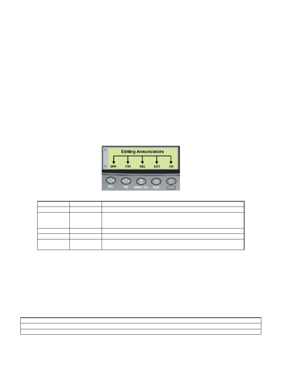
4.1 Editing Annunciators
When in Setup the instrument displays editing annunciators. Figure 13 identifies each of the editing annunciators.
When in Setup, press the corresponding keypad key below the annunciator.
Figure 13: Editing Annunciators
Annunciator Key Name
Description
GRP
ZERO
• Steps through the list of Groups.
ITM
TARE
• Steps through the list of Items.
• Press this key to accept changes and return to the menus.
• (Also refer to the OK description below.)
SEL
GROSS/NET • Moves the editing cursor in some editing modes.
EDT
• Steps through the available options when editing a particular item.
OK
OK
(FUNCTION)
• Press this key to accept changes and return to the menus.
• (Also refer to the ITM description above.)
4.2 Numeric Entry
A numeric entry box allows the input of a number. When entering a number, the display will show digits with the
currently selected digit flashing. The <SEL> key is pressed to select a digit to change. When the digit is selected
the <EDT> key is pressed to change the digit from 0 through 9. The leftmost digit can also be changed to a dash (-)
to enter a negative number. The <OK> key is pressed to accept the number that has been entered and return to the
menu item.
Upper and lower limits are placed on some entries and an entry outside this range will cause the instrument to
display dashes (i.e. - - - - - -).
Example: When in Setup follow the steps below to set Build, Max Capacity.
• Press <GRP> repeatedly to display the BUILD group.
• Press <ITM> repeatedly to display the CAP item.
• Press <SEL> to select CAP and display the current setting (e.g. 0000.00lb).