Cooper Instruments & Systems DFI 250X Digital Weight Indicator User Manual
Page 34
CF 147
30
version 1.1
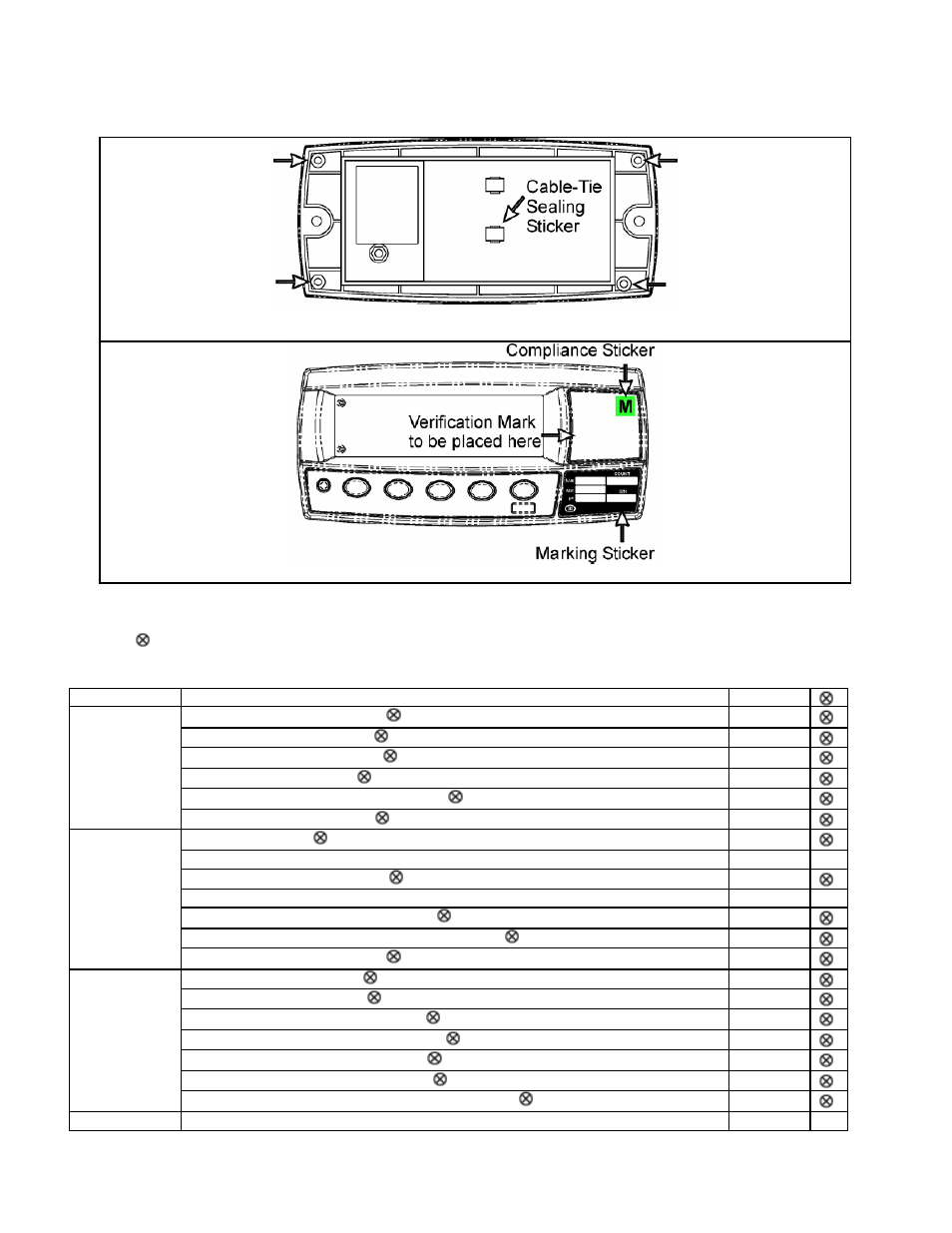
12.2 Sealing Details
Affix sealing stickers to the rear of the instrument, over one or more screws in the locations indicated.
Also affix a sealing sticker over the load cell cable where the cable-tie strain relief is attached, as indicated.
Affix stickers in the locations indicated.
12.3 Setup Menu Quick Reference
Note:
Available only in Full Setup. Changing this setting will increment the Calibration Counter.
1 Available only in Full Setup. Changing this setting will not increment the Calibration Counter.
Group (GRP) Item (ITM)
Section
DP (Decimal Point Position)
7.4.1
CAP (Maximum Capacity)
7.4.1
RES (Count -by Resolution)
7.4.1
UNITS (Weighed Units)
7.4.1
HI.RES (High Resolution x 10 mode)
7.4.1
BUILD
CABLE (4-Wire or 6-Wire)
7.4.1
USE (Scale Use)
7.4.2
FILTER (Reading Average)
7.4.2
MOTION (Motion Detection)
7.4.2
INIT.Z (Initial-Zero on Startup)
7.4.2
Z.TRAC (Zero Tracking Sensitivity)
7.4.2
Z.RANGE (Allowable Zero Operating Range)
7.4.2
OPTION
Z.BAND (Zero 'Dead' Band)
7.4.2
ZERO (Zero Calibration)
7.4.3
SPAN (Span Calibration)
7.4.3
ED.LIN (Edit Linearization Points)
7.4.3
CLR.LIN (Clear Linearization Points)
7.4.3
DIR.ZER (Direct Zero Calibration)
7.4.3
DIR.SPN (Direct Span Calibration)
7.4.3
CAL
FAC.CAL (Restore Default Factory Calibration)
7.4.3
SPEC
SAFE.PC (Safe Security Passcode for Digital Setup)
7.4.4