Assemble open-center valve – Great Plains V300 Assembly Instructions User Manual
Page 7
Great Plains Mfg., Inc.
Installation Instructions
7
11/08/2006
148-771M
Assemble Open-Center Valve
This section is for the 148-766A Open-Center (OC) kit. If
you have the 148-765A Closed-Center kit, see page 4.
Callout numbers are assigned from the “Kit Parts List”
on page 24.
Torque fittings and fasteners per “Torque Values” on
page 23.
A cluster of arrows in each diagram shows directions (T)
Top, (B) Bottom, (L) Left, (R) Right, (F) Front and (R)
Rear.
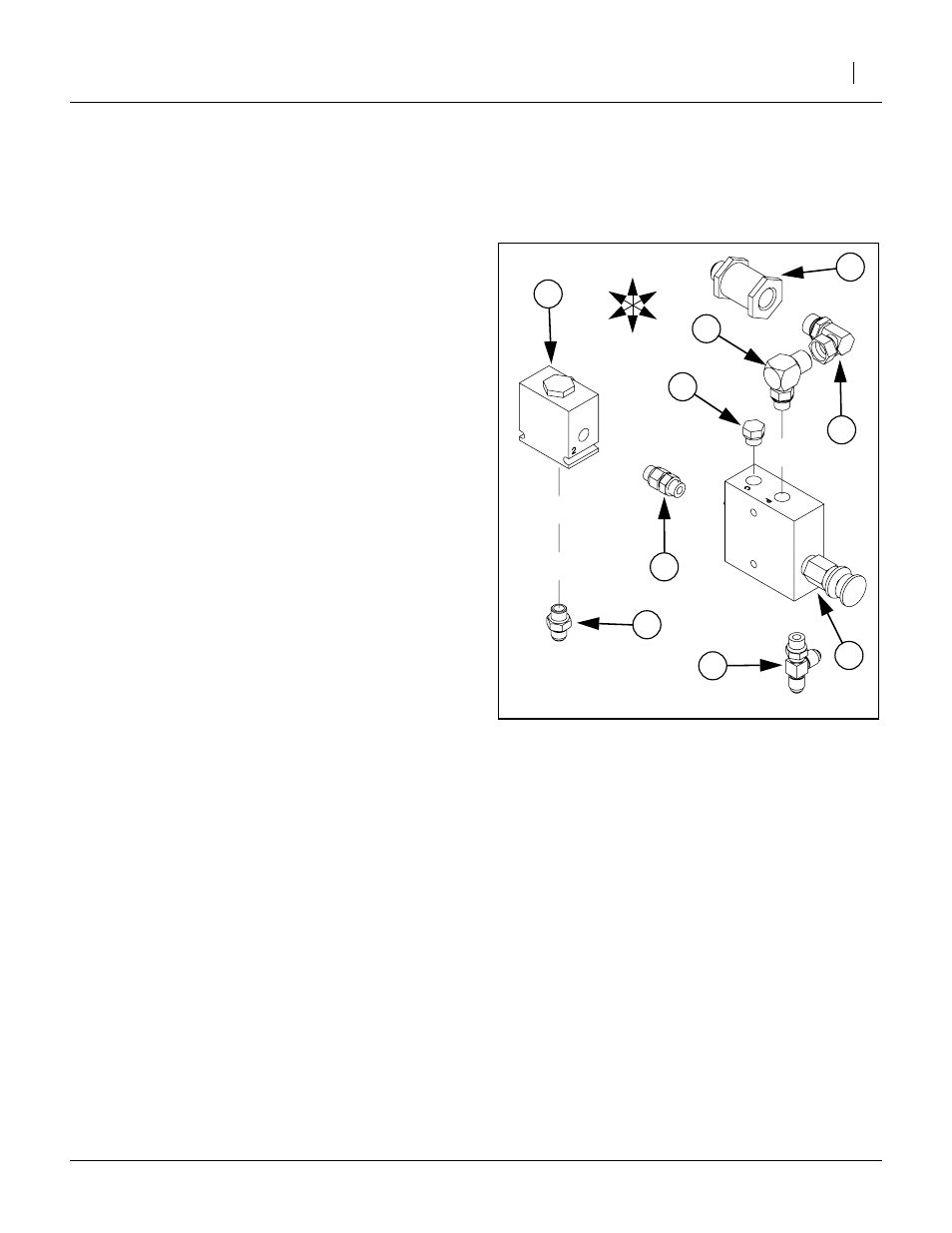
Assemble OC Down Pressure Control Valve
and Shuttle Valve
(VALVE PRESS REDUCING W/CHECK).
Orient it so that the control knob is on the Front,
toward the Bottom.
(EL 3/4MJIC 9/16MORB).
Screw the male O-ring boss end into the Top Front
port of valve body (44). Adjust the JIC end to face
Left and tighten jam nut.
(PL 9/16MORB HEX HEAD).
Screw the plug into the Top Rear port of valve body
(44) and tighten.
(AD 9/16MORB STRAIGHT UNION).
Screw the male O-ring boss end into the Rear port
of valve body (44) Do not fully tighten at this time.
(TE 9/16MJIC 9/16MJIC 9/16MORB).
Screw the male O-ring boss end into the Bottom
port of valve body (44). Adjust the tee so the center
port faces Left and tighten jam nut.
(EL 3/4FJIC 3/4MORB).
Screw the female JIC end onto fitting (58). Adjust
angle so that the ell points to the Rear, and tighten.
(FILTER INLINE 3/4FORB 3/4MJIC).
Screw it onto fitting (66) and tighten.
(VALVE PO CHECK 2:1 W/9/16FORB).
Note: The ports of valve (45) are stamped with num-
bers “1”, “2” and “3”. Orient the check valve so
that port
➁
is to the Front, port
➀
to the Rear and
port
➂
at the Bottom.
(AD 9/16MORB 9/16MJIC).
Screw the O-ring boss end into port
➂
on the Bot-
tom of check valve (45), and tighten.
53. Orient check valve (45) so that the hex nut is on
Top. Lay the Right faces of entire assembly on a
flat surface, and tighten union (63).
Figure 11
OC Down Pressure Valve
25175
T
B
R
L
F
R
➀
➁
➂