Open center operation – Great Plains V300 Assembly Instructions User Manual
Page 21
Great Plains Mfg., Inc.
Installation Instructions
21
11/08/2006
148-771M
Open Center Operation
This section covers Non-Active Hydraulic Systems -Trac-
tors with open-center hydraulic systems or fixed-dis-
placement hydraulic pumps.
If your tractor has Closed Center hydraulics, refer to
“Closed Center Field Operation” on page 19. If you are
unsure what type of hydraulic system is on your tractor,
contact your tractor manufacturer.
Note: Refer to “Post-Installation Lift Cycle” on page 17
to know what to expect the drill to do as hydraulics
are cycled.
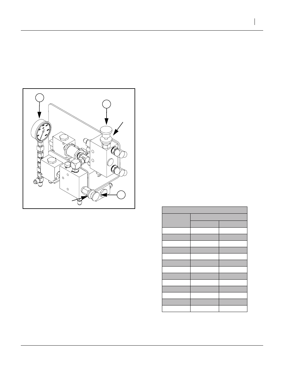
1.
Release locking disk
➀
. Close bypass valve (48) for
no oil flow by turning knob on valve clockwise com-
pletely. Always operate the drill with the bypass
valve closed. Lock disk
➀
.
2.
Lower the opener frames by pushing FORWARD on
the tractor remote hydraulic lever. The remote lever
must be TEMPORARILY LOCKED OPEN in this
position while the pressure adjustment is being
made to provide constant pressure and flow to the
openers.
John Deere tractors with Sound-Gard ® Body:
Use lever lock clip, John Deere part number
R52667, to lock lever forward. See your tractor
dealer for clip purchase and installation.
John Deere 7000 Series tractors: Rotate valve
detent selector to motor position to lock lever in for-
ward position.
John Deere 8000 Series tractors: Set timer to con-
tinuous. Push lever forward until detent clicks.
Case-IH Magnum tractors: Lock lever forward in
detent position. You may need to turn up detent
pressure to its maximum setting. Do not tie hydraulic
lever past detent position with a strap. See your trac-
tor dealer for hydraulic-system details.
Other tractors: Lock lever forward in detent posi-
tion. You may need to turn up detent pressure to
maximum or use a mechanical detent holder to hold
lever forward. See your tractor dealer for proper
means of providing constant flow to openers.
3.
Release locking disk
➁
. With the tractor hydraulic
lever locked forward, turn the knob on the pressure
control valve (44) as shown in Figure 29. Watch the
pressure gauge (43) and dial in the desired pressure
on the openers. Clockwise increases the pressure,
and counterclockwise decreases pressure. Once
the pressure is set, lock each knob with the lock disk
➁
. The recommended pressure range for drilling is
between 200 psi and 1400 psi. Setting the opener
down pressure above 1600 psi. will raise the drive
wheels off the ground when the seed box is empty
causing skips and poor seed metering. See the fol-
lowing table for the relationship between psi and
down force..
As a general starting point, set hydraulic down pressure
to 800 psi. For most field conditions, adjust down pres-
sure between 200 and 1400 psi. Setting the opener down
pressure above 1600 psi. will raise the drive wheels off
Figure 29
Open Center Valves
25186
➀
➁
Adjustment Valve Table
System
PSI
Down Force
Pounds
Kg
200
62
137
300
77
170
400
84
185
500
96
212
600
110
243
700
123
272
800
139
306
900
155
341
1000
173
380
1100
194
427
1200
217
479
1300
249
548
1400
268
591