Assemble cc valves on mount – Great Plains V300 Assembly Instructions User Manual
Page 6
Great Plains Mfg., Inc.
6
Opener Down Pressure Kit
148-771M
11/08/2006
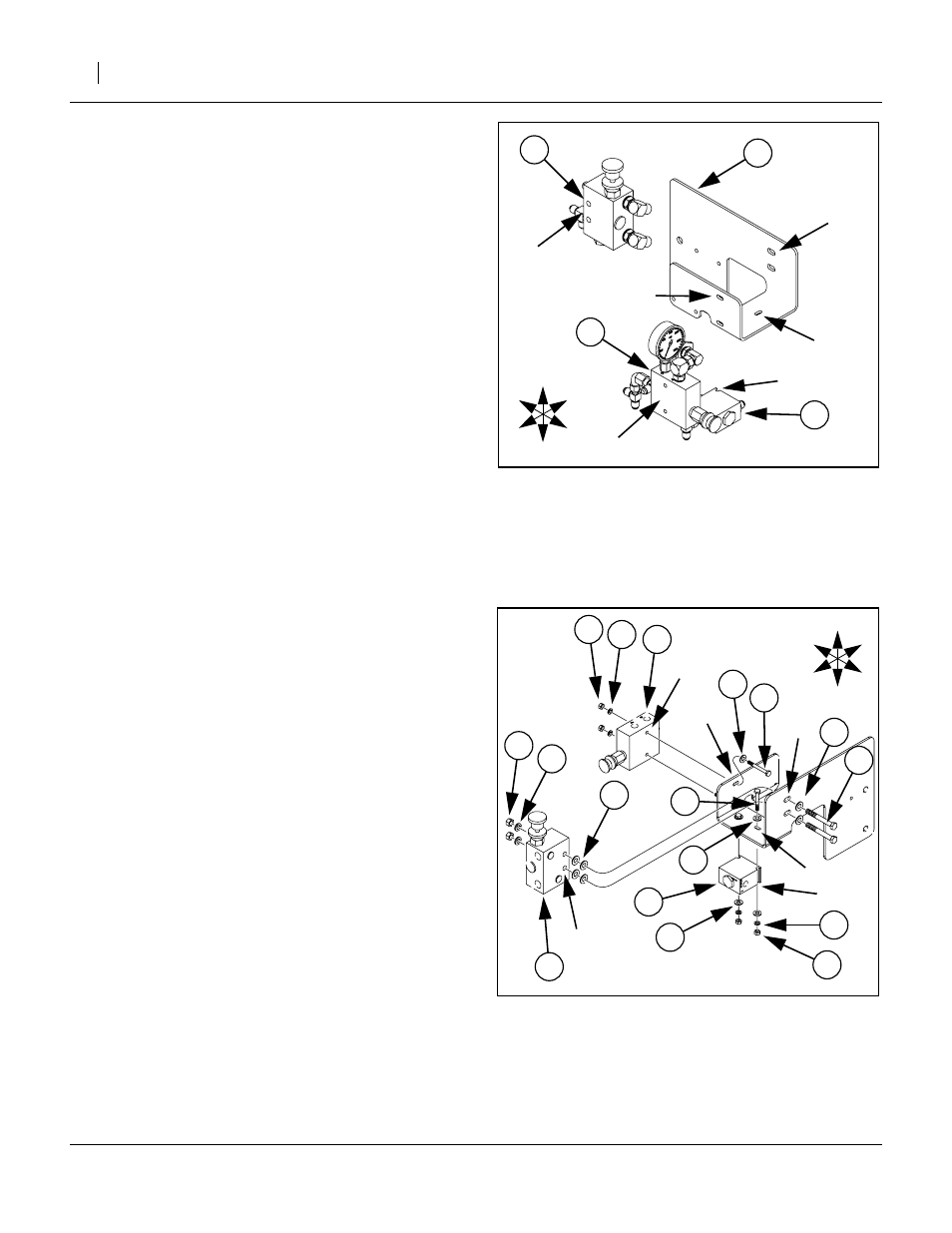
Assemble CC Valves on Mount
Refer to Figure 9 & Figure 10. Figure 10 shown exploded for clarity.
(OPNR DOWN PRESSURE VALVE MNT).
Orient it so that the smaller of the two vertical
plates is to the Right, and the horizontal base plate
is at the Bottom.
Note: Both valve assemblies mount on the Right side of
the vertical plates. The check valve mounts under
the base.
39. Align the mounting holes
➀
of the adjustment
valve assembly (44) with the holes in the small ver-
tical plate
➁
. Align the notches
➂
in the check
valve assembly (47) with the holes under the base
plate
➃
. This two valve assembly mounts outside
and under the mount.
40. Select two each:
(31) 802-551C, HHCS 1/4-20X2 1/4 GR5,
(39) 804-075C, WASHER FLAT 1/4 USS PLT,
(36) 804-006C, WASHER LOCK SPRING 1/4 PLT,
(32) 803-006C, NUT HEX 1/4-20 PLT.
From inside the mount, place a washer (39) on
each bolt (31) and insert the bolt out through plate
holes
➁
, into the holes
➀
in the adjustment valve
(44) and loosely fit a lock washer (36) and nut (32).
41. Select two each:
(31) 802-551C, HHCS 1/4-20X2 1/4 GR5,
(36) 804-006C, WASHER LOCK SPRING 1/4 PLT,
(32) 803-006C, NUT HEX 1/4-20 PLT.
and four each:
(39) 804-075C, WASHER FLAT 1/4 USS PLT,
From inside the mount, place a washer (39) on
each bolt (31), down through the plate hole
➃
into
the notches
➂
of the check valve (47) and loosely
fit another washer (39), lock washer (36) and nut
(32).
42. Snug the valve assemblies (44)(47) against the
mounting plate (23), seat bolts deeply in notches,
and tighten all bolts and nuts.
43. Select two each:
(28) 802-024C, HHCS 3/8-16X3 GR5,
(37) 804-013C, WASHER LOCK SPRING 3/8 PLT
(33) 803-014C, NUT HEX 3/8-16 PLT
Select also six:
(40) 804-087C, WASHER FLAT 3/8 HARD
ASTMF436
From the Left outside of the mount, insert each bolt
(28) through one washer (40), then through the
plate holes
➅
. Slide on two additional washers (40)
as spacers, then the bypass valve assembly (48)
via holes
➄
. Fasten with a lock washer (37) and a
Figure 9
Mount Closed Center Valves
25173
T
B
R
L
F
R
➅
➃
➂
➁
➀
➄
Figure 10
Closed Center Fasteners
25174
T
B
F
R
L
R
➂
➁
➀
➄
➅
➃