Assemble cc check valve, Assemble cc bypass valve – Great Plains V300 Assembly Instructions User Manual
Page 5
Great Plains Mfg., Inc.
Installation Instructions
5
11/08/2006
148-771M
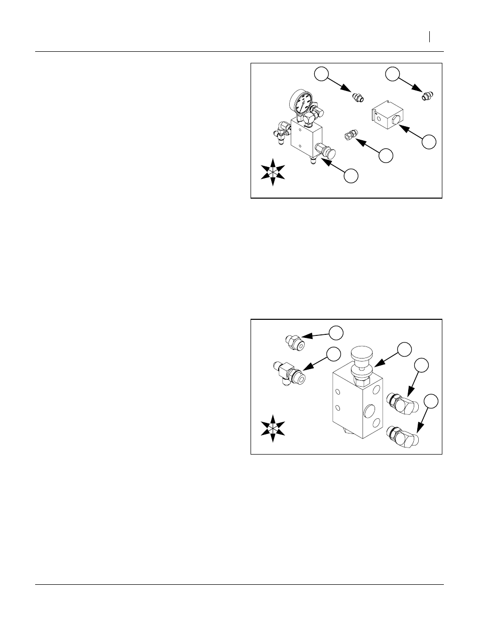
Assemble CC Check Valve
(VALVE PO CHECK 4:1 W/9/16FORB).
Note: The ports of valve (47) are stamped with num-
bers “1”, “2” and “3”. Orient the valve so that Port
➀
is to the Left, port
➁
to the Right and port
➂
to
the Rear.
(AD 9/16MORB 9/16MJIC).
Screw the male O-ring boss end into port
➀
of
valve body (44).
(AD 9/16MORB 9/16MJIC).
Screw the male O-ring boss end into port
➂
of
valve body (44).
(AD 9/16MORB 9/16FJIC).
Screw the male O-ring boss end onto check valve
assembly (47) at port
➁
. Tighten jam nut.
33. Screw the check valve assembly (47), onto the
male JIC fitting at the Bottom of adjustment valve
assembly (44). Rotate check valve assembly (47)
so that port
➂
faces Rear before tightening JIC
nut.
Assemble CC Bypass Valve
Note: Orient the valve (48) so that the adjustment knob
is on Top, toward Right and Front.
35. Select two (51) 811-063C,
(EL 3/4MJIC 3/4MORB).
Screw both into the Front ports of valve (48).
Rotate each to point to the Left and down before
tightening jam nuts.
(TE 9/16MJIC 3/4MORB 9/16MJIC).
Screw the male O-ring boss end into the Rear Bot-
tom port of valve (48). Point the center port of the
tee down before tightening jam nut.
(AD 9/16MJIC 3/4MORB).
Screw the male O-ring boss end into the Rear Top
port of valve (48).
Figure 7
CC Check Valve
25171
T
B
R
L
F
R
➂
➀
➁
Figure 8
CC Bypass Valve
25172
T
B
R
L
F
R