Weld lug, Drain hydraulic system, Caution – Great Plains V300 Assembly Instructions User Manual
Page 3
Great Plains Mfg., Inc.
Installation Instructions
3
11/08/2006
148-771M
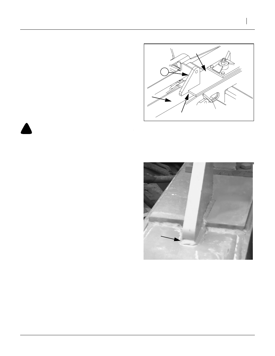
Weld Lug
5.
Select lug (25) 248-508D,
(TOP LINK CYL LUG).
6.
Temporarily position the new top link cylinder lug
(25) against the pivot plate
➀
on the drill frame
➁
.
7.
Center the lug (25) left-to-right, and push it as far
back against the pivot plate
➀
as possible before it
begins to ride up on the existing weld fillet. This
may leave a vertical gap at
➂
.
8.
Scribe the outline of the lug (25) on the pivot plate
➀
.
9.
Brush or sand the paint from the inscribed area,
plus ~1.3cm outside that area.
!
CAUTION
Use caution when using tools that emit sparks such as weld-
ers. Wear suitable protective equipment. Do not use spark-
emitting tools in areas where flammable or explosive materi-
als may be present. Do not allow anyone to enter the path of
sparks.
10. Protect any nearby hoses or cables with welding
tarps.
11. Re-position the lug (25) as in step 7. Tack-weld the
lug in two places. Re-check centering and 90
degree vertical alignment.
12. Make a high tensile strength 100% wire or stick
weld around the entire base of the lug, with a fillet
of approximately 1.3cm.
13. Allow lug to cool.
14. Brush or sand off any burrs or other weld artifacts,
and paint. Apply a metal primer if a matching green
exterior enamel paint is not immediately available.
Drain Hydraulic System
This upgrade kit is inserted in the existing hydraulic sys-
tem at two points. Removing the fittings at these two
points will result in some loss of fluid (which is why it is
important to perform this and later steps after the weld-
ing). The following steps minimize fluid loss.
15. Put the tractor hydraulic controls into “float” mode.
16. Shutdown the tractor hydraulic system.
17. Loosen the fitting at the top of the left lift cylinder,
enough to let air enter at that point.
18. Set a collection pan under the right lift cylinder.
19. Loosen the fitting there enough to begin draining
fluid into the pan.
Figure 4
Position Lug
25168
➀
➁
➂
Figure 5
Weld Lug
25169