Install cylinder – Great Plains V300 Assembly Instructions User Manual
Page 12
Great Plains Mfg., Inc.
12
Opener Down Pressure Kit
148-771M
11/08/2006
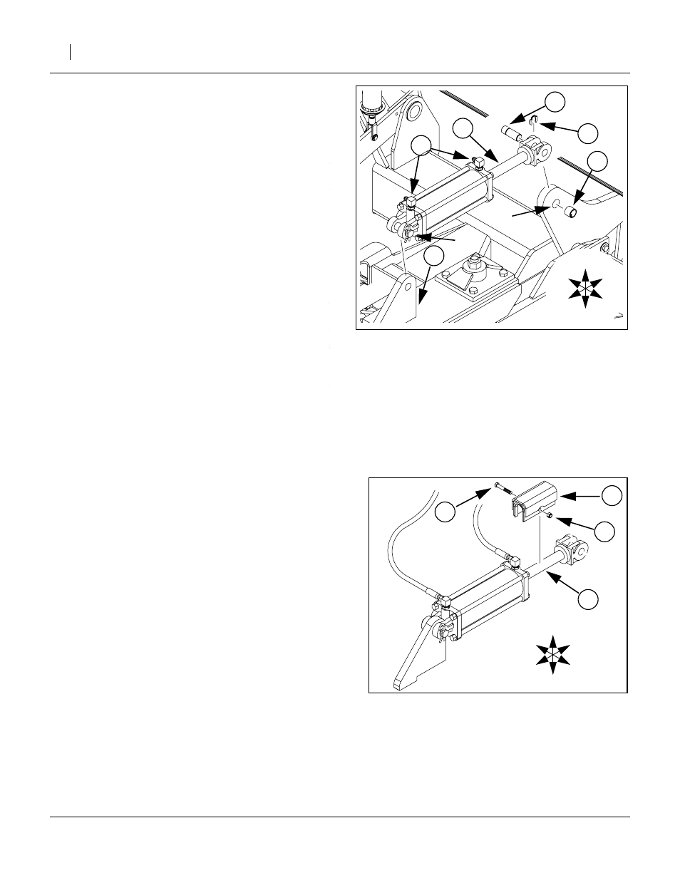
Install Cylinder
The (42) 810-162C cylinder is supplied with 1in pins
and cotter pins in the base end. There may also be a pin
in the rod end. There may also be one or two washers
on each pin. These parts are not called out separately.
(CYL 3.5X8X1.25 ROD (TIE ROD)).
Leave the protective caps in the ports.
88. If present, remove the pre-installed pin from the
rod end of the cylinder (42). This pin, cotter pin and
any washer(s) are not re-used.
89. Remove the pre-installed pin
➀
from the base end
of the cylinder (42). Save all parts.
90. Mount the base end of cylinder (42) on the frame
lug (25) welded earlier. Re-insert the pin compo-
nents removed in step 89 and secure the cotter
pin.
(BUSHING CYL 1 1/4 X 1 X 1).
Insert it inside the existing bushing in the rocker
arm
➁
.
92. Select the:
(24) 248-507D, CYLINDER PIN and
(27) 800-245C, SNAP RING EXT 1 5304
93. Remove the protective caps from the cylinder
ports. Extend and rotate the rod (42) until the clevis
holes align with the top hole in the rocker arm
➁
.
94. Insert pin (24), attaching rod (42) to rocker arm
➁
.
95. Insert snap ring (27) in between the right face of
the rocker arm and the right lug of the clevis of rod
(42). Fully seat the snap ring.
96. Select two (57) 811-171C,
(EL 3/4MORB 9/16MJIC) ells.
Install the O-ring boss ends in the cylinder ports.
Before tightening, adjust the base end fitting to
point Right and slightly toward the Rear (approxi-
mately aimed at the valve assembly location).
Adjust the rod end fitting to point Right and Front.
(5.625 CYL DEPTH CHNL ASSY).
Place it over the cylinder (42) rod, and slide to the
Rear up against the clevis end.
(HHCS 3/8-16X2 1/2 GR5) and
(35) 803-078C,
(NUT LOCK 3/8-16 NYLON INSERT).
Insert the bolt (30) in the depth channel (12) and
secure it with the lock nut (35).
Figure 19
Down Pressure Cylinder
25183
T
B
F
R
L
R
➁
➀
Figure 20
Cylinder Channel
25184
T
B
F
R
L
R