Great Plains TSF660 Operator Manual User Manual
Page 46
TSF660
500-644M
9/1/2009
44
Assembly
1.
Install forward internal bearing snap ring in mounting
frame.
2.
Press in forward bearing from rear side of mounting
frame to snap ring.
3.
Install two external shaft retainer rings with spacer be-
tween on shaft.
4.
Press shaft assembly through forward bearing until for-
ward shaft snap ring rests against inner face of forward
bearing.
5.
Press rear bearing over shaft.
6.
Insert rear internal bearing snap ring.
7.
Slide rubber slinger over shaft and push back to front
bearing.
8.
Clean old sealant from mounting frame seal bore.
9.
Install o-ring in shaft groove.
10. Apply non-hardening Type 2 Permatex or similar under
stationary seal flange.
11. Place stationary portion of seal over shaft and press into
seal bore cavity. Use 1-3/8” ID pipe or PTO adapter to
press seal flange evenly on all sides.
12. Install rotating portion of seal over shaft and o-ring by
hand. The two polished seal faces should face each oth-
er. Avoid contacting polished seal faces.
13. Insert key in keyway. Install im-
peller on shaft.
14. Place lock washer and 3/8” lock
nut on shaft and tighten nut.
15. Replace volute o-ring or gasket,
volute, and four 3/8” x 3/4” cap
screws.
16. Position coupler in pump shaft
slot and fill cavity surrounding
coupler with grease.
17. Install motor by aligning motor
tang and coupler slot. Rotate
motor until nameplate faces up.
18. Install four 5/16” cap screws.
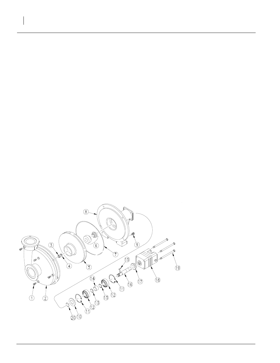
Ace Hydraulic Pump Seal Replacement
Refer to Figure 25
Disassembly
1.
Remove four 5/16” hex head cap screws from rear of
motor. Remove motor and coupler.
2.
Remove rear internal bearing snap ring.
3.
Remove four 3/8” x 3/4” hex head cap screws from
mounting frame. Remove volute.
4.
Remove 3/8” lock nut from shaft. Insert flat file into im-
peller vane to hold stationary. CAUTION: Excess
torque may cause damage to plastic impellers.
5.
Press shaft out of impeller using one 5/16” hex head
cap screw from step 1. Remove impeller, key, and ro-
tating seal member.
6.
Press shaft/bearing assembly out of frame.
7.
Remove stationary seal member by prying out with
screwdriver or pressing out from motor end of pump
housing.
8.
Remove o-ring from shaft groove.
NOTE: If only replacing the pump seal: 1) Press the
shaft/bearing assembly into frame. 2) Reinstall rear in-
ternal bearing snap ring. 3) Skip to Assembly step 8.
9.
Press bearings off of shaft.
10. Remove forward internal bearing snap ring.
Figure 25
Ace Hydraulic Pump
23373