Install casters, Pre-load stabilizers, Elevate cart – Great Plains SML1000 Operator Manual User Manual
Page 40: Mount casters
36
SML-1000, SML-750, SML-500
Great Plains Manufacturing, Inc.
407-451M
03/31/2011
Install Casters
If the cart was shipped with the entire axle removed, skip
to “Install Axle” on page 38.
Pre-Load Stabilizers
Refer to Figure 20 and Figure 21
1.
On axle weldments, loosen one jam nut
each
side (2 total).
2.
Back set screws
almost all the way up (leave
them threaded in a few turns).
3.
Select two sets:
266-012D PLATE RND 3/16" THK 1 7/8" DIA
807-290C SPRING DIE 2 OD X 5 LONG 1040#
266-020D UHMW RND 2.0 DIA X 2.0 LONG
Have masking tape at hand.
4.
Insert the plate
, then spring
then UHMW
piston
into the bottom of the stabilizer tube. Push
the piston up against the spring until the piston is at
least partly inside the tube. Place tape
down one
side of the tube, across the bottom of the piston, and
up the other side of the tube. Use enough tape to
hold it in place until casters are mounted.
Elevate Cart
5.
Hoist the cart frame high enough to swing down and
pin the parking stand (see page 14).
6.
Operate the parking stand cranks to fully extend both
feet on the stand.
7.
Support the frame at the rear axle so that the bottom
surfaces of the caster spindle tubes are at least
56 in (142 cm) off the ground.
8.
Lower the frame until stand feet are on the ground.
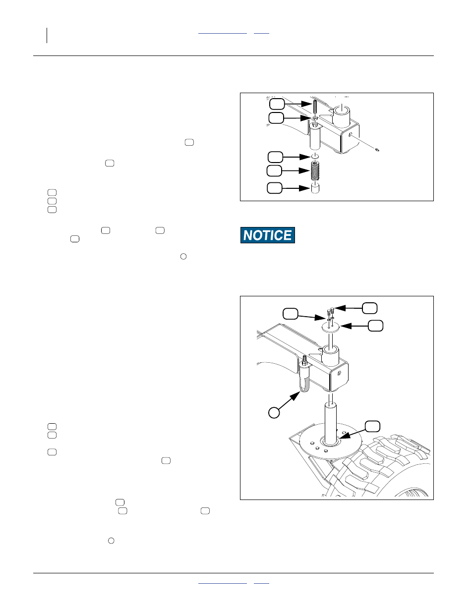
Mount Casters
On a caster assembly, remove and save two sets:
802-034C HHCS 1/2-13X1 1/4 GR5
804-015C WASHER LOCK SPRING 1/2 PLT
and one:
161-231D NTA CASTER RETAINER CAP
Do not remove the thrust washer
.
10. Use a lift or hoist to carefully insert the caster spindle
into the axle caster tube. Avoid dislodging the steel
bushings in the tubes.
11. Place the cap plate
on the top of the spindle.
Place a lock washer
on each of two bolts
.
Thread the bolts through the cap and into the spindle
a few turns.
12. Remove the tape
from the stabilizer piston.
13. Tighten the spindle cap bolts to torque spec.
Null4:
Null4:
Null4:
Paint Damage Risk:
If painter’s masking tape is not available, chose a substitute
tape that will not damage paint when removed from the stabi-
lizer tubes.
Figure 20
Pre-Load Stabilizer
31483
39
27
16
47
17
39
27
16
47
17
16
47
17
Null4:
Null4:
Null4:
Note: Either caster may be installed on either side.
They are not provided in left/right variants.
Figure 21
Mount Caster
31515
28
13
41
1
44
28
41
13
44
13
41
28
1