Double mechanical seal – Viking Pump TSM420: HL-LL 4925 User Manual
Page 8
SECTION TSM 420
ISSUE
E
PAGE 8 OF 18
8. The seal sets and rotary members of the seal may be
removed from the side opening of the bracket, see step
11, for removal of the double mechanical seal
9. Clean all parts thoroughly and examine for wear or
damage Check lip seals, ball bearing, bushings and
mechanical seal and replace as necessary Check all
other parts for nicks, burrs, excessive wear and replace
if necessary
NOTE: Be sure that the shaft is free from burrs and
foreign particles that might damage the bracket bushing
Scratches on the shaft in the seal area will provide
leakage paths under the mechanical seal
10. Check casing for wear or damage while mounted to the
bracket
NOTE: Pay particular attention to the location,
arrangement and construction of the seal parts as it will
help considerably when the pump is re assembled
12. Remove the seal cap if it was not removed in step 6 A
light tap may be necessary to loosen it
13. The O-ring gaskets of the seal sets may have become
slightly sealed against the side of the housing and
require extra effort If this happens, apply light oil in the
seal housing bore in front of the seats so they will slide
freely
14. After removing the outer seal seat, the outer rotary
member, the spring and the inner rotary member can be
removed
15. Remove the inner seal seat and gasket by bending the
ends of the two lengths of wire and then by inserting the
bent end in the slots in the bushing and pulling the seal
seat through the housing from the shaft end If removal is
difficult, an arbor press may be used to push the bracket
bushing, seal seat and gasket out of the bore from the
rotor end Another coating of light oil may be helpful to
ease the seal seat out of the housing
Another way of removing the inner seal seat is to drive
it out while inserting a screwdriver through the bracket
bushing from the casing end so it hits the seal seat at the
notches in the bracket bushing Be careful and do not
damage the bracket bushing when removing the inner
seal seat in this manner
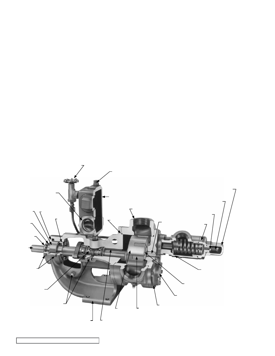
DOUBLE MECHANICAL SEAL
fIgURE 9
See figure 11. The mechanical seal consists of five basic
parts They are: inner and outer seal seats with O-ring
gaskets; inner and outer rotary members; and spring
When pump is running the seal cap and inner and outer
seal seats with O-ring gaskets remain stationary in the
bracket seal housing bore; the inner and outer rotary
members turn with the shaft
11. The pump has now been disabled to the point where the
double mechanical seal may be removed from the seal
housing bore of the bracket
END CAP
SETSCREWS
IDLER PIN
CASINg
O-RINg
OIL RESERVOIR
OIL fILLER PLUg
HAND VALVE
SIgHT
gLASS
INNER
END
CAP
OUTER
END
CAP
THRUST
BEARINg
LOCK
WASHER
LOCKNUT
SHAfT
OIL
DRAIN
PLUgS
POPPET
LOCKNUT
ADJUSTINg
SCREW
ADJUSTINg
SCREW CAP
RETURN-TO-TANK
RELIEf VALVE
BRACKET
BRACKET BUSHINg
ROTOR
IDLER
DOUBLE
MECHANICAL
SEAL
HEAD
IDLER BUSHINg
VALVE COVER PLATE