Pressure adjustment, Disassembly assembly, Danger – Viking Pump TSM420: HL-LL 4925 User Manual
Page 13
SECTION TSM 420
ISSUE
E
PAGE 13 OF 18
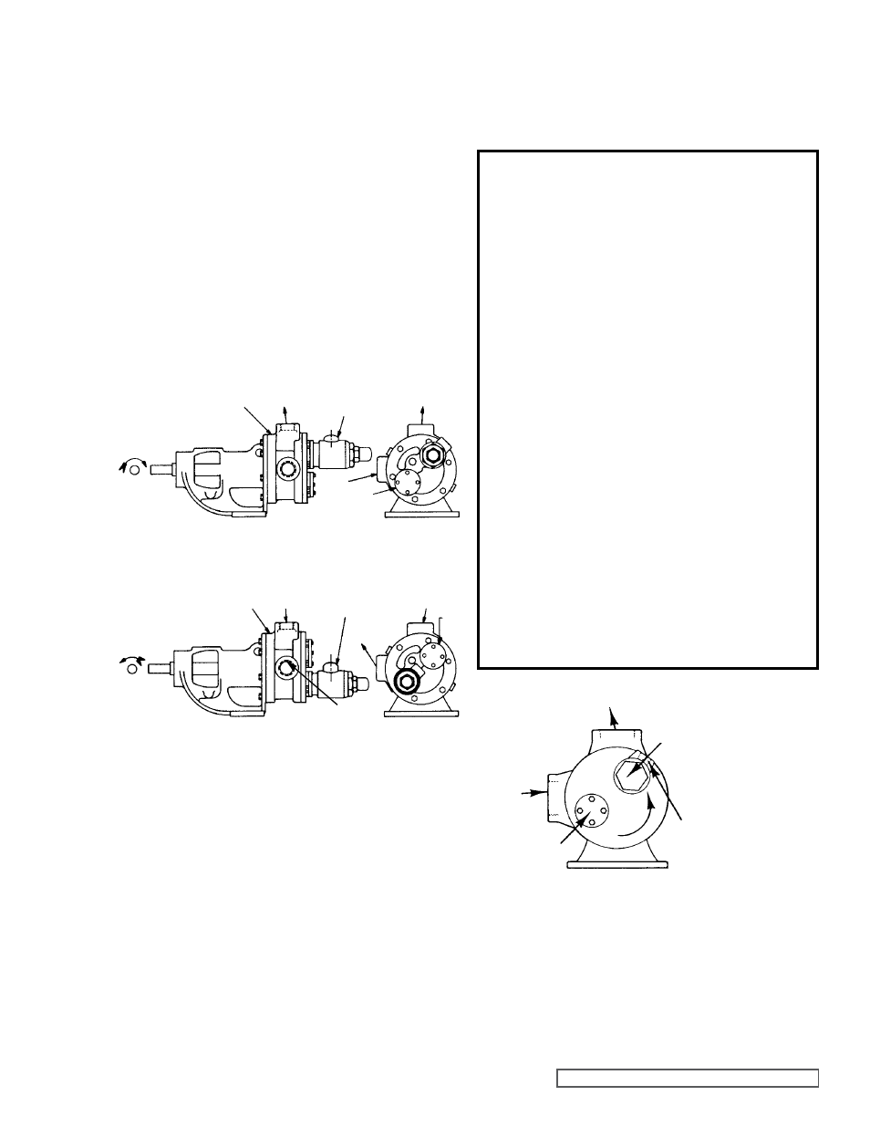
figure 19 shows the standard pump rotation (clockwise)
When viewing the shaft end, the inlet port is on the right and
the outlet on the top
If the pump rotation is reversed as shown on
figure 20 to give
counter clock rotation is reversed as shown in
figure 20 to
give counter clockwise rotation when viewing the shaft end,
the inlet port is on the top, and the outlet port on the right
On “HL” size pumps equipped with Return-To-Tank pressure
valves,
(see figure 17) the cap should point towards the
suction side of pump
On “K” - “LL” size pumps equipped with return-to-tank
pressure relief valves,
(see figure 18) the valve must always
be mounted on the valve port nearest the pump discharge
port,
see figure 21. Valve port nearest the pump inlet port
must be covered with the valve cover plate
If the pressure setting of the valve is to be changed from that
which the factory has set, the following instructions should be
carefully followed:
PRESSURE ADJUSTMENT
fIgURE 20
fIgURE 21
DANgER !
Before opening any Viking pump liquid
chamber (pumping chamber, reservoir,
etc.) Be sure:
1. That any pressure in the chamber has
been completely vented through the
suction or discharge lines or other
appropriate openings or connections.
(See detailed procedure for venting
the pumps, pages 4, 5 and 6).
2. That the driving means (motor,
turbine, engine, etc.) has been
“locked out” or made otherwise non-
operational so that it cannot be
inadvertently started while work is
being done on the pump.
3. That you know what liquid the
pump has been handling and the
precautions necessary to safely
handle the liquid. Obtain a material
safety data sheet (MSDS) for the
liquid to be sure these precautions
are understood.
failure to follow above listed
precautionary measures may result in
serious injury or death.
NOTE: Mark the valve and head, or casing, to be sure they
are reassembled in the same relative position
1. Remove valve cap
2. Measure and record the length of extension of the
adjusting screw
3. Loosen the lock nut and back out adjusting screw until
spring pressure is released
4. Remove the bonnet, spring guide, spring and poppet
from valve body Clean and inspect all parts for wear or
damage and repair or replace as necessary
Reverse the procedure outlined under disassembly If valve
is removed for repairs, be sure to replace in same position
DISASSEMBLY
ASSEMBLY
fIgURE 19
Remove the valve cap, which covers the adjusting screw,
and loosen the lock nut which locks the adjusting screw so
pressure setting will not change during operation of pump
A pressure gauge somewhere in the discharge line must be
used for actual adjustment operation The adjusting screw
should be turned for increasing the pressure or turned out for
decreasing the pressure With the discharge line closed at a
point beyond the pressure gauge, the gauge will show the
maximum pressure the relief valve will allow while the pump
is in operation
RETURN-TO-TANK VALVE
RETURN-TO-TANK
VALVE
VALVE PORT
COVER PLATE
CASINg
OUT
IN
IN
OUT
IN
RETURN LINE
TO TANK
CONNECTS
HERE
VALVE PORT
COVER PLATE
RETURN-TO-TANK
VALVE
COVER
PLATE
CASINg
OUT
OUT
IN
BRACKET