Pump installation – Viking Pump TSM420: HL-LL 4925 User Manual
Page 3
SECTION TSM 420
ISSUE
E
PAGE 3 OF 18
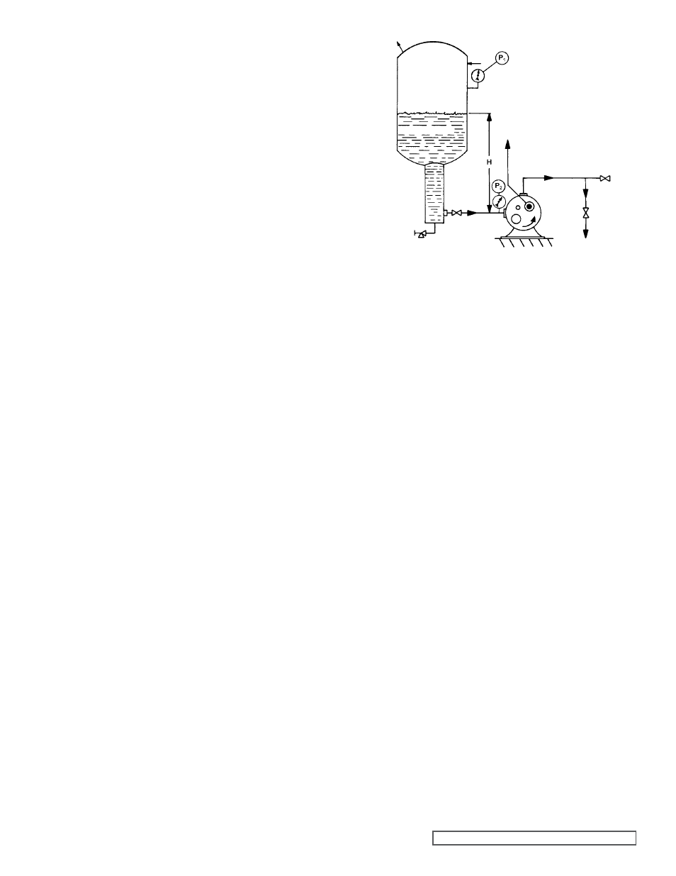
fIgURE 2
4. PUMP SPEED - The slower the operating speed the
longer the longer the service life This is particularly true
on refrigeration ammonia pumps where:
4.1. the liquid has virtually no lubrication value or film
strength to prevent surface to surface contact and,
4.2. the heat generated by friction can cause the ammonia
to vaporize, which in turn causes cavitation
5. TESTING - All Viking Ammonia pumps are tested prior
to shipment, but it is good practice to pressure test the
pump along with the rest of the system before adding
the ammonia Shipping, storage and installation all have
strange ways of producing detrimental effects on sound
equipment
6. SYSTEM CLEANLINESS - Ammonia is a good
detergent, as such it has a tendency to remove all
the dirt, pipe scale, weld beads, and loose or foreign
material in the system Unfortunately not all of this
material settles out in traps or can be caught in strainers;
and as a result, a considerable amount goes through the
pump, the abrasive solids going through the pump will
of course cause excessive wear during the start up of
a new system, thus the cleaner a new system is before
start up, the less wear and trouble with the pump
7. STAND BY EQUIPMENT - Stand by equipment is always
good insurance when possible breakdown of any single
piece of equipment could be jeopardise the operation of
the entire system Often on circulating, two pumps are
used, with operation of the pumps alternated by day or
week Alternating operation of the pumps is not always
considered the best practice since both pumps may both
wear out at the same time If operation of the pumps
is not alternated, the stand by pump should be run for
several hours at least once a month to make sure it is in
good operating condition Sometimes on large systems
three pumps are used, two running continuously, with
the third for use as a standby and for peak loads
One of the most important considerations on any circulation
Refrigeration Ammonia pump installation is proper design of
the pump inlet line Refrigeration Ammonia, when stored in
a closed container, will exert a pressure within the container
equal to its saturated vapor pressure The saturated pressure
of a liquid may be defined as the pressure at which both liquid
and vapor exist in equilibrium in the same container The
vapor pressure has a different value for each temperature
The saturated vapor pressure of water at 212ºF (waters
boiling point) is 14 7 PSIA In other words, when handling
Refrigeration Ammonia, we are handling a liquid, which is at its
boiling point A slight reduction in the pressure being exerted
on the liquid will cause boiling and thus vapor formation
With this information in mind let us examine figure 2, which
illustrates one of the most important considerations when
installing a pump to handle Refrigeration Ammonia
The pressure (P1) in the accumulator is equal to the
saturated vapor pressure of the ammonia When the pump
is not running the pressure (P2) at the pump inlet is equal to
the tank pressure (P1) plus the static head (H) P2 = P1 + H
As soon as the pump started and the liquid begins to flow, the
pressure at the pump (P2) will drop by an amount equal to
the pressure loss in the piping between the accumulator and
the pump When liquid is flowing: P2 = P1 + H - (pressure
loss in the piping)
In order to have an installation in which the pump handles all
liquid and no vapor, the pressure drop in the piping must be
equal to or less than the static head (H) on the pump inlet If the
piping loss is greater than the static head, the liquid ammonia
will start to boil or vaporize and the pump will be required to
take in a mixture of liquid and vapor Since a given weight of
vapor takes up a much greater volume than the same weight
of liquid, handling both liquid and vapor will reduce the liquid
output from the pump The vapor is compressed back to a
liquid on the discharge side of the pump causing it to be noisy
and to wear rapidly
Values for pipe friction losses for calculating suction line
pressure drop can be found in refrigeration hand books
Since Viking pumps are of the positive displacement type, be
sure that there is no obstruction in the discharge line and that
all valves are in operating position before starting the pump
Factory assembled port will have right hand port suction and
top port discharge unless otherwise specified Port location
is determined by looking at shaft end of pump The pressure
relief valve on the pump provides over pressure protection
Return-to-Tank pressure relief valves should be mounted on
the discharge side of the pump Internal type pressure relief
valves should be mounted with the cap pointing towards the
suction side of pump Also see formation under
Relief Valve
Instructions page 12. The Viking pump mounted return-to-
tank pressure relief valve
(see figure 16, PAgE 11 & figure
17, page 12) is fitted with a pressure relief plug to keep a
valid off return line from building up excessive pressures
PUMP INSTALLATION
ACCUMULATOR
PUMP