Assembly – Viking Pump TSM420: HL-LL 4925 User Manual
Page 10
SECTION TSM 420
ISSUE
E
PAGE 10 OF 18
1. Installing a new seal: The seal is simple to install and
good performance will result if care is taken in installation,
see figure 11, page 9 for parts identification
Seals made by different manufacturers are used in these
pumps and are used interchangeably though they may
look different and have a different spring
After all parts have been examined and cleaned or
replaced as necessary the first step in reassembling the
pump is installation of the inner seal seat
Good performance will result if care is taken during
installation
NOTE: Never touch the sealing faces with anything
except the fingers, cardboard or clean soft cloth
5. After replacing the casing on the bracket, place the rotor
and shaft into the casing
NOTE: If the casing is removed from the bracket, be
sure the bracket O-ring is in place before placing casing
on bracket
6. Place the O-ring or head gasket on the head
7. Start the head assembly with idler and bushing in place,
into the pump, push in as far as it will go, then replace
the capscrews and tighten
8. Place the tapered installation sleeve (furnished with
replacement seals K-LL size) on the shaft as shown in
figure 14.
9. Clean and oil the I D of the inner rotary member, place
on shaft and slide over the tapered installation sleeve
into position against the inner seal seat Push against
the rubber tail section of the bellows with a sleeve or
smooth piece of pipe having an inside diameter no more
than ¹
⁄₃₂ inch larger than the shaft diameter and a wall
thickness of at least ¹
⁄₈ inch Be sure to install correct
end against seal seat,
see figure 11, page 9. Be sure
carbon face does not fall out of the rotary member
10. Slide the spring along the shaft and make sure it seats
properly over the inner rotary member It may be helpful
to stand pump on end to facilitate centring the spring
11. Coat the outer seal seat and O-ring gasket with light
Refrigeration Oil Spread a thin film of grease on the seal
cap Place the outer seal seat in position on the seal cap
Make sure the pin in the seal seat engages the hole in
the seal cap The film of grease will hold these two parts
together, set them aside temporarily
12. Coat the inside diameter of the outer rotary member with
light Refrigeration Oil Place it over the shaft and slide it
far enough to engage the spring Be sure to install the
correct end towards the spring,
see figure 11, page 9.
13. Quickly install the outer seal seat and cap prepared
in step 11 over the shaft and press down against the
outer rotary member until the seal cap hits the end of the
bracket This compresses the spring and positions the
outer rotary member Do not release the seal cap
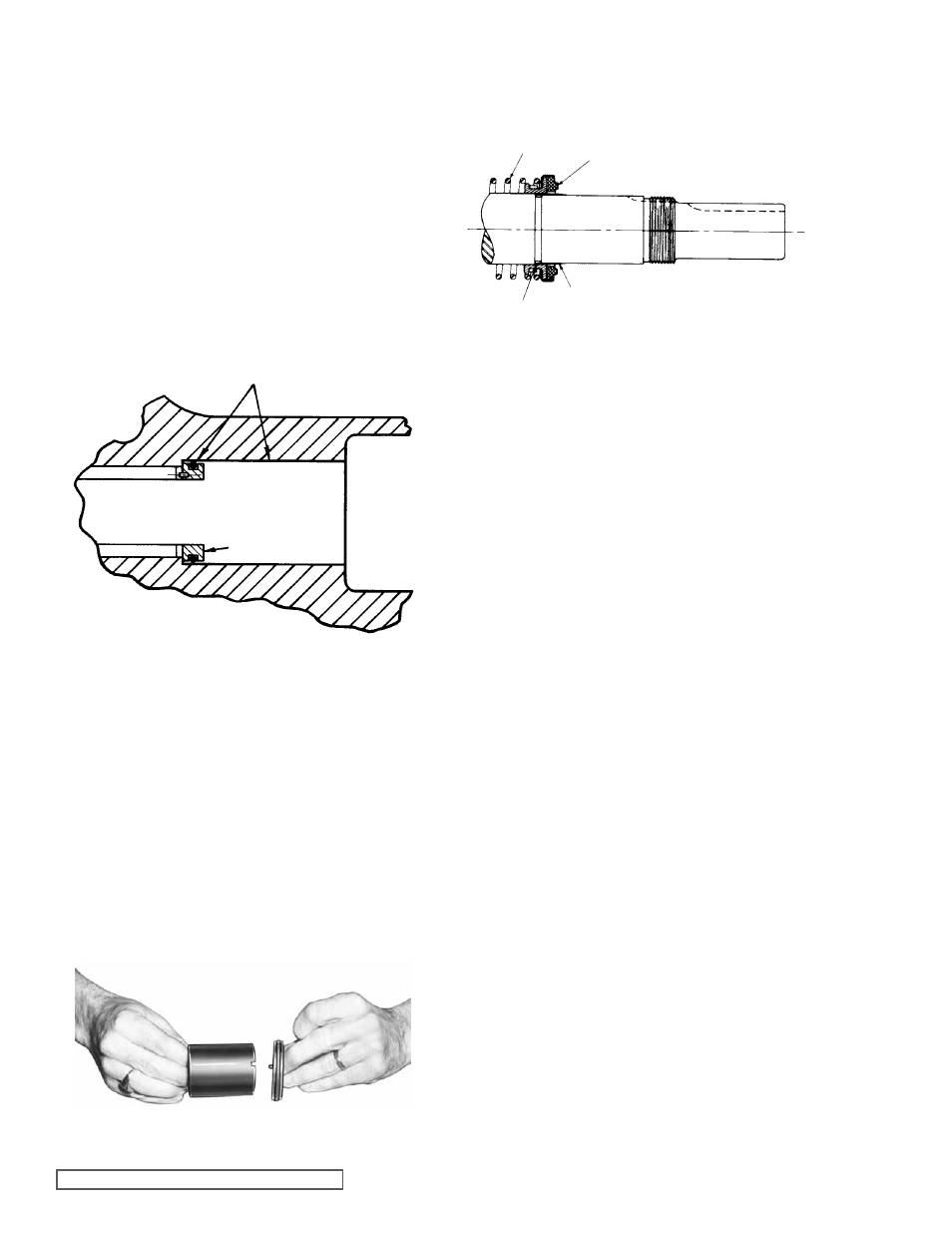
2. Clean the bracket seal housing bore, making sure it is
free of dirt and grit
3. Coat the outside of the inner seal seat and O-ring gasket
and also the inside diameter of the real housing bore
with light Refrigeration Oil (not grease),
see figure 12.
Press the inner seal seat with O-ring gasket into place
in the seal housing bore with your fingers or by putting a
piece of card board over the face of the face of the seal
seat and press with a block of wood or squared off piece
of pipe Remove the cardboard
figure 13 shows how
the inner seal seat pin fits into either of the slots in the
end of the bracket bushings Be sure the pin engages
one of these slots in the bushing when you have finished
pushing the seal seat into the seal housing bore Check
by looking through the bracket bushing from the casing
end
ASSEMBLY
fIgURE 12
fIgURE 13
fIgURE 14
4. Clean and coat the pump shaft with light Refrigeration
Oil Check to be sure no scratches have been cot into the
shaft in the seal area
COAT WITH LIgHT OIL
BEfORE ASSEMBLY
SEAL HOUSINg BORE
INNER SEAL SEAT
AND gASKET
SPRINg
MECHANICAL SEAL
(OUTER ROTARY MEMBER)
COAT WITH LIgHT OIL
BEfORE ASSEMBLY
TAPERED SLEEVE