Viking Pump TSM420: HL-LL 4925 User Manual
Page 12
SECTION TSM 420
ISSUE
E
PAGE 12 OF 18
When installing a new carbon graphite idler or graphite
bushing, extreme care should be taken to prevent breaking,
as it is a brittle material and easily cracked If cracked the
bushing will simply disintegrate
NOTE: Using a lubricant and adding a chamfer in the bushing
and the matting part will help in the installation of carbon
graphite bushings
An arbor press should always be used for installing carbon
graphite bushings Be sure bushing is started straight and
DO NOT STOP pressing operation until bushing is in proper
position Starting and stopping will invariably result in a
cracked bushing
INSTALLATION Of CARBON
gRAPHITE BUSHINgS
PRESSURE RELIEf VALVE
INSTRUCTIONS
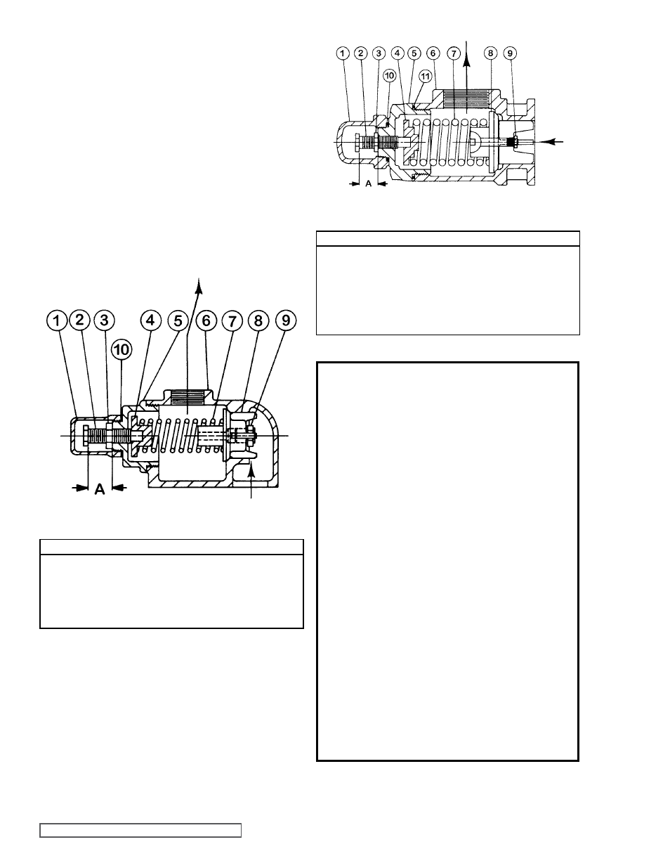
fIgURE 17
fIgURE 18
VALVE - LIST Of PARTS
1 Valve Cap
7 Valve Spring
2 Adjusting Screw
8 Poppet
3 Lock Nut
9 Pressure Relief Plug
4 Spring Guide
10 Cap Gasket
5 Bonnet
11 Bonnet Gasket
6 Valve Body
VALVE - LIST Of PARTS
1 Valve Cap
6 Valve Body
2 Adjusting Screw
7 Valve Spring
3 Lock Nut
8 Poppet
4 Spring Guide
9 Pressure Relief Plug
5 Bonnet
10 Cap Gasket
DANgER !
Before opening any Viking pump liquid
chamber (pumping chamber, reservoir,
etc.) Be sure:
1. That any pressure in the chamber has
been completely vented through the
suction or discharge lines or other
appropriate openings or connections.
(See detailed procedure for venting
the pumps, pages 4, 5 and 6).
2. That the driving means (motor,
turbine, engine, etc.) has been
“locked out” or made otherwise non-
operational so that it cannot be
inadvertently started while work is
being done on the pump.
3. That you know what liquid the
pump has been handling and the
precautions necessary to safely
handle the liquid. Obtain a material
safety data sheet (MSDS) for the
liquid to be sure these precautions
are understood.
failure to follow above listed
precautionary measures may result in
serious injury or death.