Disassembly assembly thrust bearing adjustment – Viking Pump TSM420: HL-LL 4925 User Manual
Page 14
PUMP
SIZE
Turn Outer End Cap C.C.W.
No. of Notches* or Length on O.D., Inches
HL
2
¹
⁄₂”
K - HL
4
1”
SECTION TSM 420
ISSUE
E
PAGE 14 OF 18
The Viking Over-Pressure Relief Valve is strictly an over-
pressure relief valve; it is not a pressure regulating valve
In ordering parts for relief valve on head, always be sure
to give Model and Serial Number of the pump as it appears
on the nameplate (secured to the pump) and the name of
the part wanted When ordering springs, be sure to give the
pressure setting desired
VIKINg OLD SERIES 924 HEAVY-DUTY
REfRIgERATION AMMONIA PUMPS
THRUST BEARINg DISASSEMBLY,
ASSEMBLY AND ADJUSTMENT
1. Loosen radial set screws in the outer ring of the bearing
housing and remove the bearing housing end cap, lip
seal and bearing spacer collar Use a spanner wrench to
remove the end cap
2. Remove the double row ball bearing The bearing should
be washed thoroughly and examined If there is any
evidence of wear or damage, a new bearing should be
used
3. Examine the lip seal in the bearing housing and end
cap These lip seals are important to the assembly and
should be replaced if not in first class condition They are
a grease seal for the ball bearing and also act as a shield
to keep dirt and other abrasive particles from entering
the bearing When installing new lip seals, be sure they
are assembled with the lips facing toward the shaft end
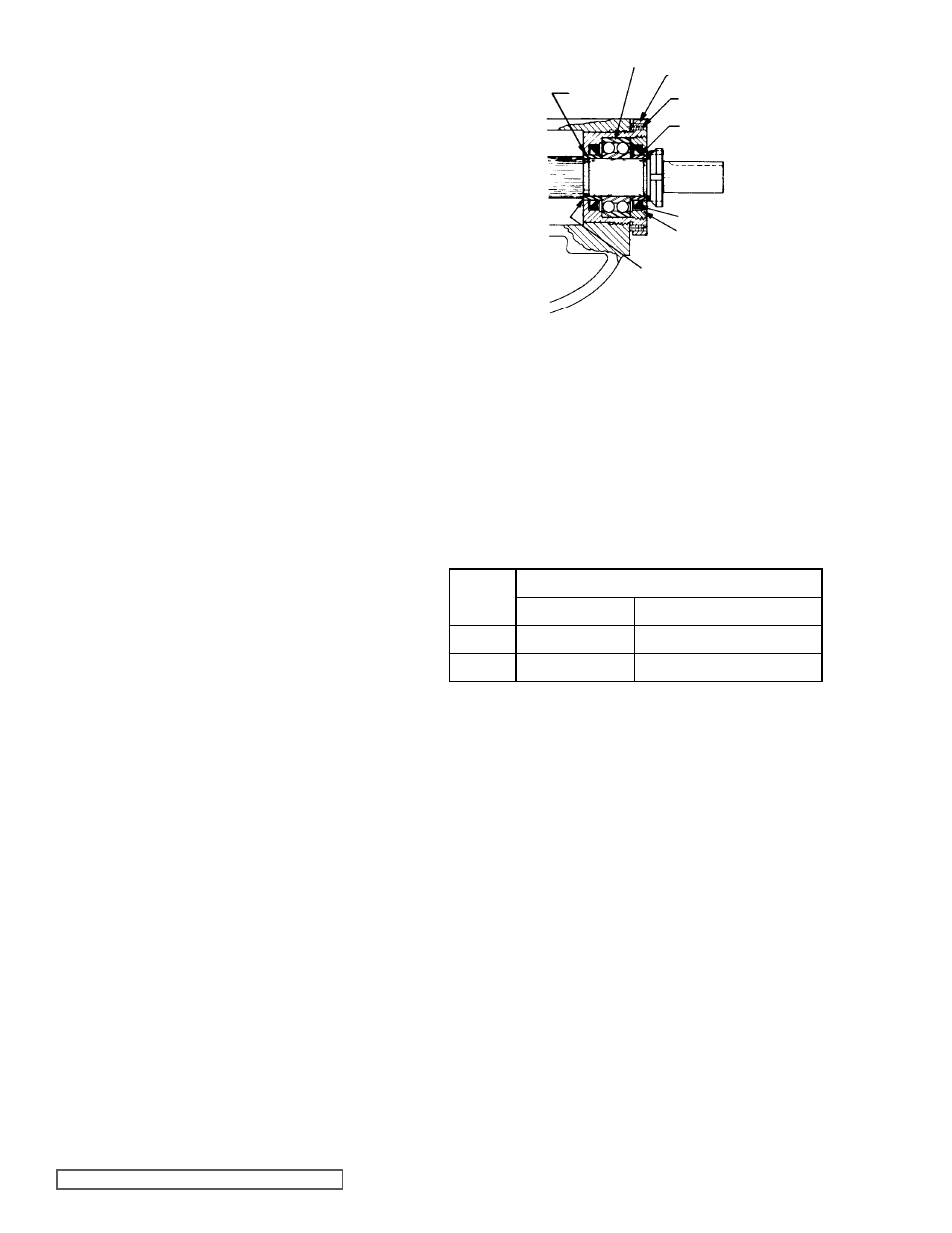
See figure 22.
Return to page 8, step 8, for further disassembly
1. Place the inner bearing spacer collar on the shaft as far
as it will go
NOTE: First replace the snap ring or keeper rings if
furnished in your pump
See figure 22.
2. Install the bearing housing with inner lip seal into the
bracket
NOTE: If bearing housing has not been disassembled
or has been pre-assembled skip items 3 and 4
3. Pack the ball bearing with grease, place on the shaft and
push or gently drive into place in the housing
4. Turn the bearing housing end cap (with lip seal and
bearing collar inside) into the bearing housing until it is
tight against the bearing Lock in place by tightening the
radial set screws in the outside diameter of the bearing
housing
5. Turn the bearing housing assembly clockwise until pump
shaft can no longer be turned by hand The rotor is now
forced against the head
6. Install the lockwasher and locknut on the shaft, tighten
lock nut and bend down tang of the lockwasher into slot
of locknut
NOTE: A piece of brass or wood inserted through the
port opening between the rotor teeth will keep the shaft
from turning
1. Loosen two axial set screws in the outer face of the
bearing housing and turn the thrust bearing assembly
clockwise until it can no longer be turned by hand Back
off counter clockwise until the rotor and shaft can be
turned by hand with a slight noticeable drag
2. For standard end clearance, back off the thrust bearing
assembly the required number of notches or an equivalent
length measured on the outside of the bearing housing
See the following table
3. Tighten the two axial set screws in the out board face of
the bearing housing, with equal force against the bracket
Your pump is now set with standard end clearance and
locked
NOTE: Be sure the shaft can rotate freely If not, back off
additional notches and check again
4. Each additional notch (or each ¼” on the outside diameter
of the bearing housing) is equivalent to an extra end
clearance of 002” on HL size pumps; and 0015” on K,
KK, LQ and LL size pumps
5. Insert the pipe plug (drain) into the bracket Close the
hand valve and fill with oil reservoir with 1½” of the top
with lighter Refrigeration Oil It is recommended that the
oil be drained and the reservoir be refilled after the first
100 hours of operation and then after every 1000 hours
NOTE: Re-open the hand valve before the pump is into
operation The double mechanical seal will not function
properly, if it is exposed to ammonia pressure with the
valve closed
6. Return to installation of Carbon Graphite Bushings, page
13, and continue on
DISASSEMBLY
ASSEMBLY
THRUST BEARINg ADJUSTMENT
fIgURE 22
SETSCREW
SHAfT
LIP SEALS
BEARINg HOUSINg
SPACER
COLLAR
(INNER)
BALL BEARINg
SNAP RINg OR
KEEPER RINg
END CAP
SPACER
COLLAR
(OUTER)