Thrust bearing adjustment – Viking Pump TSM420: HL-LL 4925 User Manual
Page 11
PUMP
SIZE
Turn Outer End Cap C.C.W.
No. of Notches or Length on O.D., Inches
HL
3
¹
⁄₂ ”
K - LL
5
²¹
⁄₃₂
”
SECTION TSM 420
ISSUE
E
PAGE 11 OF 18
14. Still holding the seal cap against the end of the bracket,
place half-moon shaped seal holder plate in position and
tighten the two locknuts uniformly This holds the seal
cap in position and insures proper positioning of seal
NOTE: Do not permit either the inner or outer rotary
member to remain in the shaft in any position other than
their final position for more than 30 seconds since the
rubber bellows of the rotary members have a tendency
to stick to the shaft If the bellows are not in correct
position, the rotary member will be improperly seated
15. Remove tapered sleeve
16. Place the inner bearing spacer collar on the shaft as far
as it will go
NOTE: First replace the snap ring (“HL” size) or half
round rings (“K” - “LL” size) if furnished see figure 15
1. Loosen the square head setscrews over the outer and
inner end caps (two for the HL size, four for the K thru HL
size pumps)
2. Turn the inner end cap clockwise (viewed from shaft
end) until it projects slightly from the bracket exposing
approximately three threads
3. Turn the outer end cap clockwise until the rotor is tight
against the head and the rotor shaft cannot be turned
4. Make a reference mark on the bracket end, opposite a
notch on the other end cap Back off the outer end cap
the required number of notches shown in the table,
see
figure 16.
5. Tighten the inner end cap with a spanner wrench Tap the
spanner wrench lightly but
DO NOT OVER TIgHTEN,
as it will only damage the threads
6. Tighten all the square head setscrews that hold the
inner and outer end caps to prevent their turning in the
bracket
7. The rotor and shaft should turn smoothly for one complete
revolution If the rotor and shaft doesn’t turn smoothly, go
back and repeat the Thrust Bearing Adjustment steps 1
thru 7
17. Press the lip seal (lip toward end of shaft) into the inner
cap and insert the end cap through the shaft end of
bracket With two fingers turn it clock wise (looking at end
of shaft) until it engages the threads The spanner holes
in the wrench cap must be toward the rotor Turn the end
cap with a spanner wrench until it projects slightly into
the opening on the side of the bracket
NOTE: The end cap must not be turned so far that the
lip of the seal drops off the end of the spacer collar on
the shaft or the end cap becomes disengaged with the
threads
, see figure 15.
18. Pack the ball bearing with multi-purpose grease, place
on the shaft and push or gently drive into place in the
bracket
19. Install the lip seal (lip toward end of shaft) and bearing
spacer in the outer end cap and turn the end cap to the
bracket until tight against the bearing,
see figure 15.
*For Viking Old Series 924 Heavy-Duty Refrigeration
Pumps see page 16 for bearing housing disassembly,
assembly and adjusting instructions
20. Put lockwasher and locknut on shaft Insert length of
hardwood or brass through port opening between rotor
teeth to keep shaft from turning Tighten locknut to 50-70
ft - lbs Torque (HL) or 100-130 ft - lbs Torque (K - LL)
THRUST BEARINg ADJUSTMENT
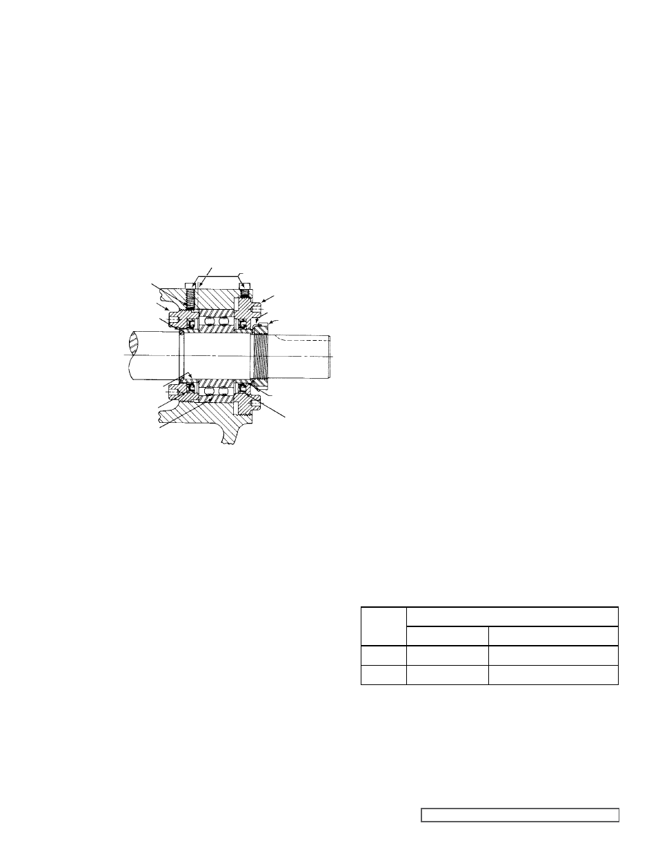
fIgURE 15
fIgURE 16
Bend one tang of lockwasher into slot of locknut If tang
does not line up with slot, tighten locknut until it does
Failure to tighten locknut or engage lockwasher tang
could result in early bearing failure and cause damage
to rest of pump
Remove length of hardwood or brass from port opening
21. Adjust the pump end clearance as indicated in THRUST
BEARINg ADJUSTMENT, below
22. Insert the pipe plug (drain) into the bracket Close the
hand valve and fill the reservoir to within 1½ inches of
the top with the light Refrigeration Oil It is recommended
that the oil be drained and the reservoir be refilled after
the first 200 hours of operation and then after every 1000
hours
NOTE: Re-open the hand valve before the pump is
put into operation The double mechanical seal will not
function properly if it is exposed to ammonia pressure
with this valve closed
SHAfT
LOCKNUT
gREASE fITTINg LOCATION
HALf ROUND
RINgS
INNER
END CAP
NYLON INSERT
SETSCREWS
OUTER END CAP
LOCKWASHER
OUTER SPACER
COLLAR
INNER SPACER
COLLAR
OUTER
LIP SEAL
BALL
BEARINg
INNER LIP SEAL