Disassembly, Danger – Viking Pump TSM420: HL-LL 4925 User Manual
Page 7
SECTION TSM 420
ISSUE
E
PAGE 7 OF 18
4. Loosen the two locknuts and remove the seal holder
plate For parts identification,
see figure 7.
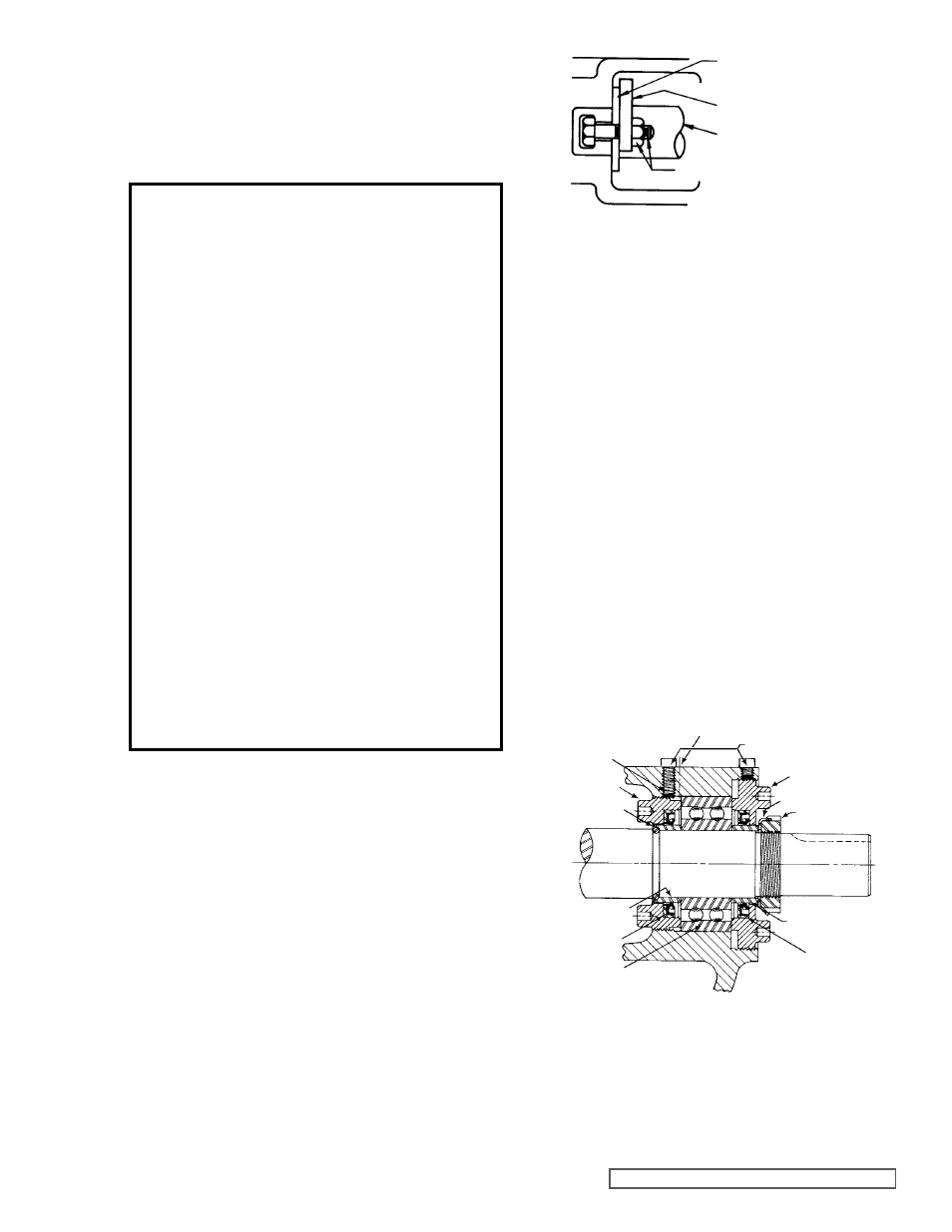
5. Drive the shaft forward approximately ½” and check the
pair of half round rings (“K” - “LL” size) under the inner
bearing spacer collar or a snap ring (“HL” size) at the
end of the inner bearing spacer collar,
see figure 8.
NOTE: The snap ring (“HL” size) or half round rings (“K”
- “LL” size) must be removed before the rotor and shaft
can be removed from the pump These rings will not pass
through the mechanical seal and bracket bushing
6. Carefully remove the rotor and shaft As the shaft is
being removed decreasing shaft diameters tend to allow
the shaft to drop onto the bracket bushing To avoid
damaging the bracket bushing, support the rotor and do
not allow either end of the shaft to tilt downward
NOTE: Considerable force may be required to remove
the rotor and shaft from the pump Be careful as not to
damage seal parts as the rotor and shaft is removed
Some of the seal parts may fall off when the rotor and
shaft are removed Place them to the side to be put with
other mechanical seal parts when they are removed
7. Loosen the four setscrews over the outer and inner end
caps Remove both end caps, ball bearing and bearing
spacer collars
See figure 8.
fIgURE 7
fIgURE 8
DISASSEMBLY
12. When all venting has stopped continue with removing
the pump from the system or disassembly of the pump in
place
*See asterisk, page 6
NOTE: BE SURE TO READ PAGES 4 THRU 7 PRIOR TO
PUMP DISASSEMBLY
1. Mark head and casing before disassembly to insure
proper reassembly The idler pin, which is offset in pump
head, must be positioned toward and equal distance
between port connections to allow for proper flow of
liquid through pump
Remove head from pump
Do not allow idler to fall from idler pin Tilt top of head back
when removing to prevent this Avoid damaging head
gasket If pump is furnished with pressure relief valve,
it need not be removed from head or disassembled at
this point
Refer to Pressure Relief Valve Instructions,
page 12.
2. Remove idler and bushing assembly from the idler pin
3. Bend up the tang on the lockwasher and, using a
spanner wrench, remove the lockwasher and locknut
NOTE: A piece of brass or wood inserted through the
port opening and between the rotor teeth will keep the
shaft from turning
DANgER !
Before opening any Viking pump liquid
chamber (pumping chamber, reservoir,
etc.) Be sure:
1. That any pressure in the chamber has
been completely vented through the
suction or discharge lines or other
appropriate openings or connections.
(See detailed procedure for venting
the pumps, pages 4, 5 and 6).
2. That the driving means (motor,
turbine, engine, etc.) has been
“locked out” or made otherwise non-
operational so that it cannot be
inadvertently started while work is
being done on the pump.
3. That you know what liquid the
pump has been handling and the
precautions necessary to safely
handle the liquid. Obtain a material
safety data sheet (MSDS) for the
liquid to be sure these precautions
are understood.
failure to follow above listed
precautionary measures may result in
serious injury or death.
NOTE: The inner end cap can be removed through the
side opening in the bracket
For Viking old series 924 Heavy Duty Refrigeration
Ammonia Pumps go to page 16 for bearing housing
disassembly instructions
SEAL CAP
SEAL HOLDER PLATE
SHAfT
LOCKNUT & CAPSCREW
SHAfT
LOCKNUT
gREASE fITTINg LOCATION
HALf ROUND
RINgS
INNER
END CAP
NYLON INSERT
SETSCREWS
OUTER END CAP
LOCKWASHER
OUTER SPACER
COLLAR
INNER SPACER
COLLAR
OUTER
LIP SEAL
BALL
BEARINg
INNER LIP SEAL