Viking Pump TSM420: HL-LL 4925 User Manual
Page 6
SECTION TSM 420
ISSUE
E
PAGE 6 OF 18
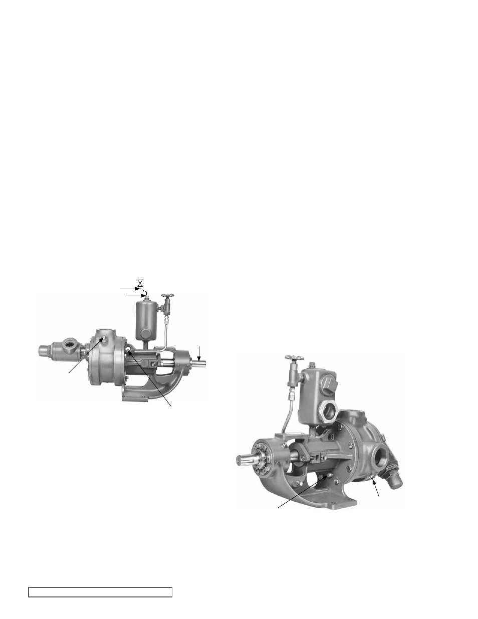
fIgURE 5
Viking K4925
Refrigeration Ammonia Pump with Return-To-Tank
Pressure Relief Valve
4. Close all other shut off valves in lines connected to the
pump Typical would be valve C in
line E* in figure 4
from the pump mounted return-to-tank type relief valve
to the accumulator or the valve from an in line mounted
safety relief valve to the accumulator or the valve in a
pressurizing
line 2 in figure 5, from the high pressure
side of the system to the pump double sea oil reservoir
5. Allow ice on pump to melt This process can be speeded
up by running cold water over the pump
Start the venting process as soon as convenient after the
ice has been removed from the pump This will prevent
venting the ammonia at the lower pressures of a cold
pump rather than at the high vapor pressures in a room
temperature pump
For systems with vent (purge or bleed) valves
(e.g. D
figure 4) go to step 6; for systems without a vent valve,
go to step 7
6. A hose should be connected to any vent valve (e.g. D
in figure 4) in the blocked off portion of the system The
open end of the horse should be placed under water in a
tank containing at least 10 times as much water as there
is ammonia in the blocked off portion of the system or the
end of the hose should be lead to a safe, well ventilated
area After the hose has been attached to the open end
properly located, then open the vent valve Check the
open end of the hose to make sure the ammonia is
venting After ammonia has stopped venting, continue
with step 8
If there is no line from the bracket to the reservoir, carefully
loosen the pipe plug (drain),
3 in figure 6 towards the
bottom of he bracket This pipe plug is found only on the
“K”, “KK”, “LQ” and “LL” 4925 pumps The small “HL”
4925 does not have one When working on the “HL”
4925 that has no trouble fitting between the bracket and
double seal oil reservoir, carefully loosen the pipe plug,
4 in figure 6, in the suction port of the pump
*This segment of line,
(E in figure 4) between the return
to tank pressure relief valve and the shutoff valve, C,
should include a pressure relief valve vented to a safe
area
8. Carefully loosen any unions or tubing fittings in any other
lines to the pump that have been blocked off by closing
the shutoff valves, so that venting from these segments
of the system can be accomplished Typical of such lines
would be that from the pump mounted return-to-tank
relief valve to the accumulator,
E* in figure 4, or a line, 2
in figure 5, from the high pressure side of the system to
the double seal oil reservoir
ALWAYS LISTEN fOR THE “PSST” AT ANY POINT
LOOSENED TO PROVIDE VENTINg.
9. Carefully loosen the fill plug 5 in figure 5, in the top of
the double seal oil reservoir
10. After the ammonia has stopped venting turn the pump
shaft,
6 in figure 5, over for at least 10 complete
revolutions This will make sure that there is no pocket of
accumulated ammonia that has not been exposed to a
venting point
11. Carefully loosen the plugs, 4 in figure 6 and 7 in figure
5, in the suction and discharge ports of the pump If
ammonia continues to vent, wait until the venting stops
When venting from all the loosened connections stops,
then complete the loosening of the fittings and complete
the removal of the plugs
fIgURE 6
Viking K4925
Refrigeration Ammonia Pump with Internal
Pressure Relief Valve
7. If there are no vent valves in the blocked off piping, the
Viking Model 4925 ammonia pump should be vented by
carefully loosening the fitting
(1 in figure 5) on the lower
end of the tubing that runs from the pump bracket to the
double seal oil reservoir
THERE SHOULD BE A DISTINCT “PSST” SOUND
WHEN THE AMMONIA VAPOR LIQUID STARTS TO
VENT. LEAVE THE AREA UNTIL THE VENTINg IS
COMPLETE.
If there is rigid pipe instead of tubing running from the
pump bracket to the double seal oil reservoir, the pipe
union should be loosened carefully until the “psst” is
heard
⑤
②
①
⑦
⑥
③
④