Tweco Troubleshooting Power Supply User Manual
Page 7
7
For resistor pilot units where the pilot current is controlled by the main inverter,
Pilot Enable causes PCB5 to connect Pilot Demand to the inverter signal I_REF.
See section on Eagle 100-300 Demand Signals – Cutting & Pilot for
troubleshooting.
For Chopper Pilot units Pilot Demand is sent from CN33-3 (CN33-4 common)
to CN2-3 chopper. See section on Eagle 100-300 Demand Signals – Cutting &
Pilot for troubleshooting.
Pilot Regulator Defective
If chopper has bias power, Pilot Demand and is enabled but still no pilot it may
be defective. It can either just not be working or can be shorted.
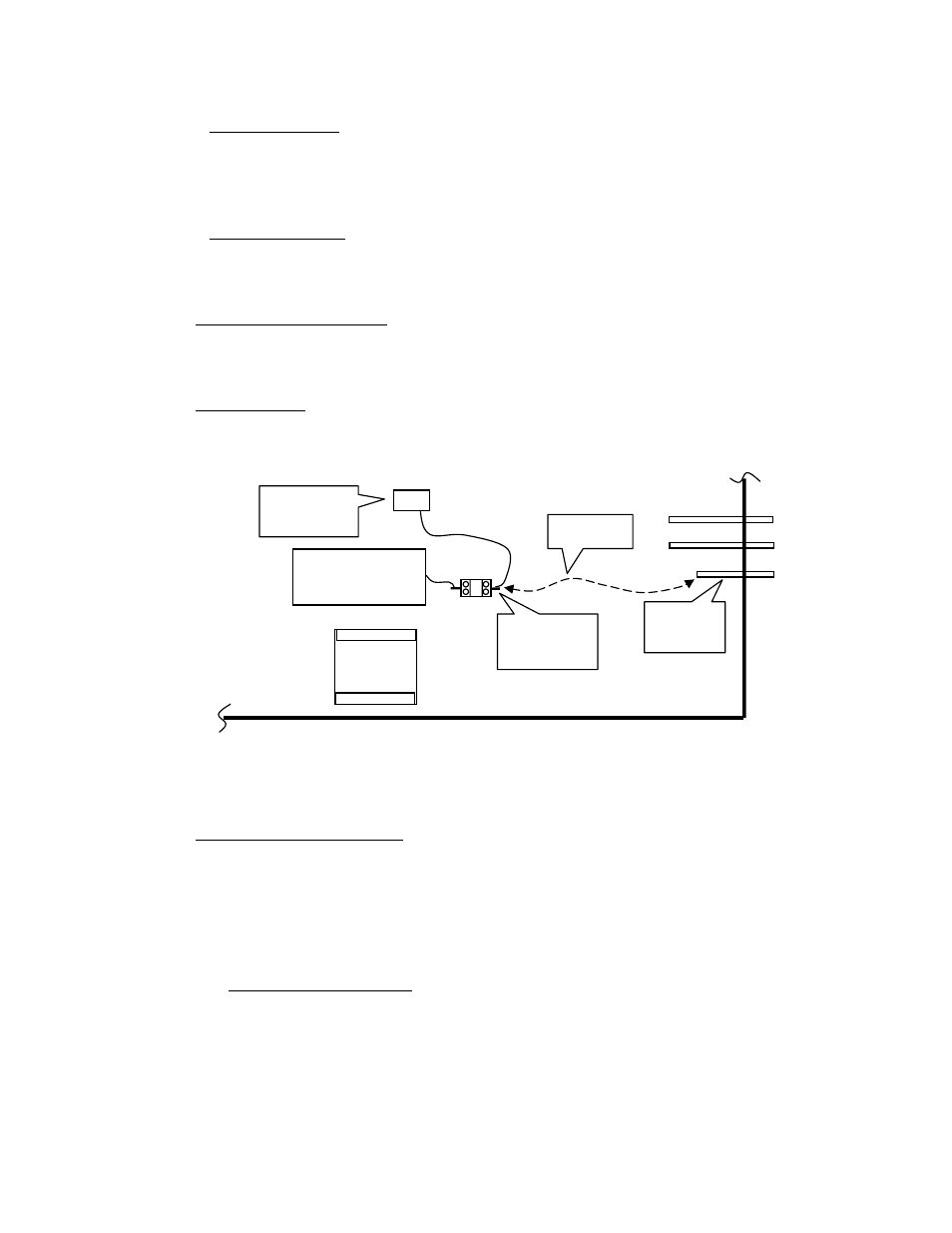
A quick test is to bypass the chopper. Connect a jumper wire capable of 30A
between the pilot busbar (where the pilot lead connects to the power supply) and
the anode of D2. Set the output current to 30A to keep the pilot current low.
Pilot only, DO NOT TRANSFER. If the torch pilots the problem is in the
chopper.
More detailed chopper tests.
To test chopper disconnect the cable to the arcstarter at J59 of the power
supply rear panel. Connect voltmeter between busbars under the cover on the rear
panel where the Torch (negative) and Pilot (positive) leads connect. Attempt to
start the unit. If voltage is equal to OCV (open circuit voltage), around 300-
400VDC, chopper is either working or shorted. If voltage is about ½ the OCV
chopper is not working.
Test for shorted chopper.
• First turn off input power and jumper across diode D2 (mounted on the
chassis to the rear of the chopper). Leave jumper on for a couple minutes
to insure chopper capacitors bleed down to zero volts.
• Chopper freewheel diodes. Measure resistance between TB2 and TB4 on
chopper. Expect to see over 20K ohms with it slowly increasing as it
Chopper
Pilot
Contactor
Pilot
Busbar
D2
Anode
Jumper
T1