Tweco Troubleshooting Power Supply User Manual
Page 12
12
measure resistance between terminals marked R2 and +. Should measure be
hundreds or thousands of ohms. A short will read less than 100 ohms.
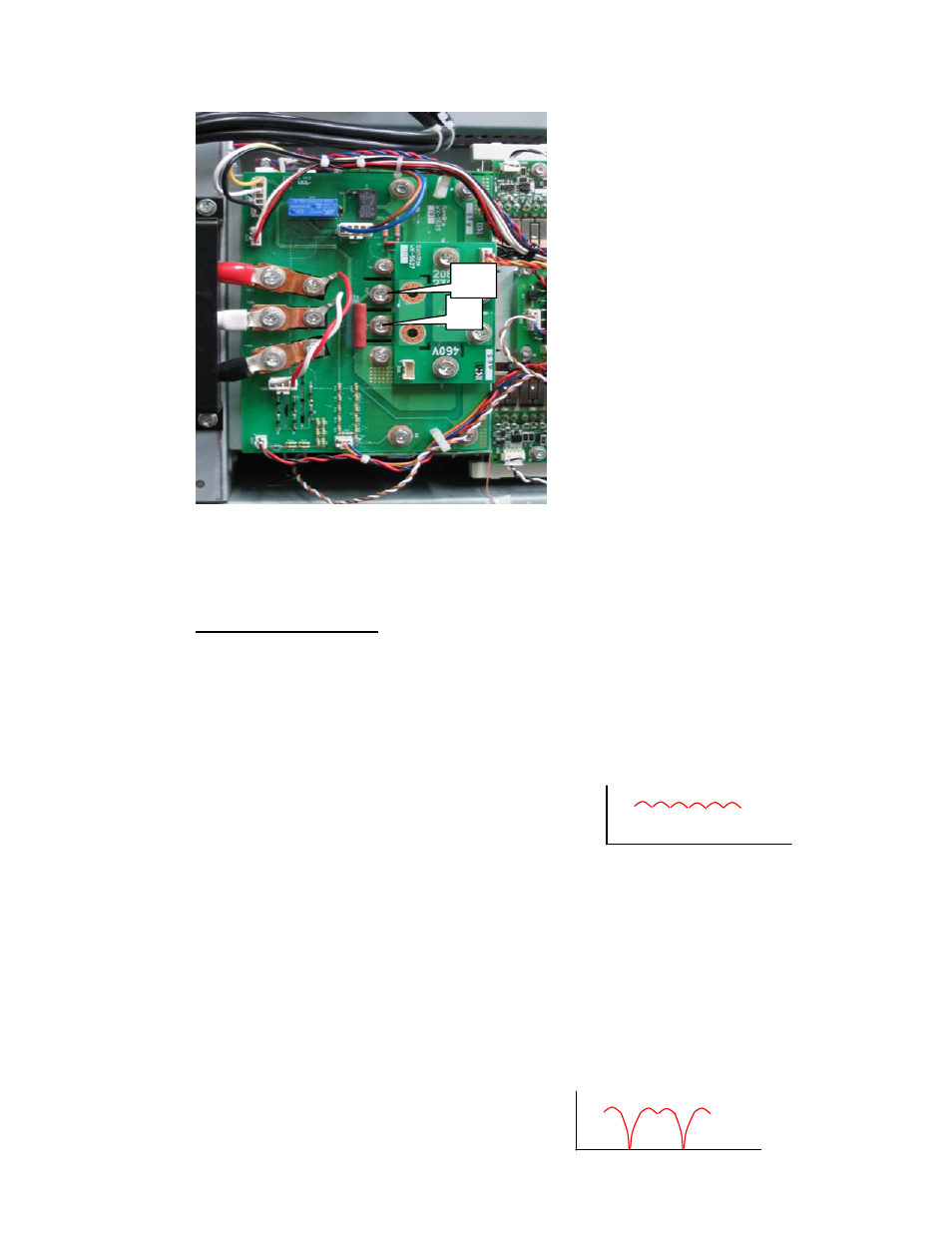
Power supply boards
Look on PCB5, WK-5602A, for LED2, Missing Phase, illuminated brightly.
When phase is not missing will still be on but not so bright. (Don’t blame me, I
didn’t design it.) If not, problem is likely in the CCM but still could be in the
output side of PCB5.
PCB4, WK-5604, has signal VACIN derived from rectifying 3 phase input on
PCB1 (Refer to simplified schematic in section 2-2). VACIN is normally a 3
phase full wave rectified DC level with little ripple. Looks like this:
Voltage that becomes VACIN comes from PCB1 and
goes to CN2-1 on PCB3 where it is passed directly to PCB4 which is daughter
board that plugs into PCB3.
VACIN can be measured on PCB3 (WK-5694) between CN2-1 (+) and PGND
at CN2-2 (-). PGND may also be found at CN1-1 which may be easier to use than
CN2-2.
Note, CN2 must be connected while taking this measurement.
VACIN should be between 7.7 to 9.5V for 460 VAC or 4.3 to 4.7 V for 208-230
VAC Power. For units with 400V input voltage (CE & CCC units) VACIN
ranges from 6.25 to 8.25V. 600V? If a phase is missing it will be somewhat
lower.
When a phase is missing VACIN looks like this:
+
R2