Quick fixed automation series torches, 01 installation – Tweco Quick Fixed User Manual
Page 10
3-6
Quick fixed automation series torches
SM-QFTORCH
INSTALLATION AND DISASSEMBLy
SECTION 3:
INSTALLATION AND DISASSEMBLY
3.01 Installation
1. Remove the torch and cable assembly from the carton,
and lay the assembly n a straght and untwsted poston
on a workbench or floor.
2. Check to ensure all tems shown n Fgure 2-1 & 2-2
on Page 2-5 are located and dentfied. If any of the
component parts are mssng, please notfy the local
Tweco
®
Weldng Dstrbutor or Tweco
®
Products Customer
Care Department at 1-800-426-1888.
3. Verfy that the overall cable length s correct to fit between
the feeder - torch mount combnaton.
4. The QF seres torch and cable assembles are furnshed
wth a 1-5/8” (41,28mm) Ø mountng dameter and can
be keyed n place nto a fixture f so desred.
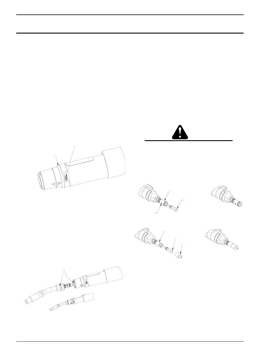
5. Rotate the front sleeve cover to expose the stanless steel
set screw located n the torch block assembly. Insert the
factory suppled 5/32” T-handle allen wrench nto the set
screw and rotate counterclockwse untl t stops as shown
n Fgure 3-1.
ROTATE FRONT SLEEVE COVER
TO EXPOSE SET SCREW, ROTATE
COVER TO CONCEAL SET SCREW
PRIOR TO TORCH OPERATION.
SET SCREW
(5/32" ALLEN KEY
Art # JB-00008
Fgure 3-1: Conductor Tube Lockng Set Screw
6. Insert the conductor tube assembly nto the torch block
assembly. The conductor tube s postvely located nto
the torch body by the use of two stanless steel algnment
pns.
7. Push the conductor tube assembly nto place untl the
stanless steel set screw can drve the back plug on the
conductor tube nto ts locked operatng poston. The
conductor tube has a machned locatng groove around
ts rear dameter. Ths groove wll be flush wth the front
housng when properly nstalled as shown n Fgure 3-
2.
WHEN CONDUCTOR TUBE IS FULLY SEATED,
GROOVE ON TUBE SHOULD LINE UP WITH
EDGE OF INSULATING SLEEVE.
Art # JB-00009
Fgure 3-2: Conductor Tube Installaton
8. Remove the gas dffuser, tp, and nozzle from the
conductor tube assembly.
9. The torch and cable assembly comes wth the Mller
®
rear
connector plug nstalled. If the feeder requres a dfferent
rear connector plug, select the correct rear connector
plug for the feeder beng used and thread the plug nto
the rear of cable assembly. Ths connecton should be
wrench tght.
10. The QF Seres torch and cable assembles are furnshed
wth R45-116 condut and the rear connector plugs to
fit ths seres of condut. If a dfferent condut and rear
connector plug s requred, refer to Page 8-18 lstng the
varous conduts that are avalable.
11. Remove the condut from the package and uncol carefully.
CAUTION
Bending or distorting the conduit can cause wire
feed problems.
12. Loosen the set screw located on the Tweco, Panasonc
®
and Lncoln
®
rear connector plug to ensure the condut wll
feed through properly. For Mller
®
style plug, remove the
threaded connector plug npple from the rear connector
plug on the torch assembly. Refer to Fgure 3-3 & 3-4.
SET SCREW
TWECO PLUG
CONDUIT ASSEMBLY
Art # JB-00010
Fgure 3-3: Condut Installaton wth Set Screw
MILLER PLUG
CONDUIT ASSEMBLY
PLUG NIPPLE
Art # JB-00011
Fgure 3-4: Condut Installaton wth Plug Npple (Mller
®
style)
13. Insert the factory-suppled 5/32” T-handle Allen wrench
through the hole on the alumnum front handle cap,
dentfied as “Condut Set Screw” on the label, and rotate
the set screw counterclockwse untl t stops rotatng.
14. Insert the exposed raw col end of the condut, factory
suppled, nto the rear connector plug. Feed the condut
through the gun and conductor tube assembly. If the
condut attempts to hang up, rotate the condut lner
counterclockwse whle gently pushng.
15. When the condut s completely through the torch and
conductor tube assembly, seat the brass condut stop
firmly aganst the connector plug.