Transmig vaf4hd – Tweco VAF4HD Transmig User Manual
Page 48
TRANSMIG VAF4HD
INSTALLATION, OPERATION AND SETUP
3-30
Manual 0-5269
3.19 Installing and Changing the Feed Roll / Removing Inlet Guide & Euro Adaptor
WARNING
MOVING PARTS can cause injury.
Make sure wirefeeder is switched OFF Before changing feedrolls, guides or adaptors.
NOTE
Feed rolls often come with a rust prohibitive coating that needs to be cleaned off before installation.
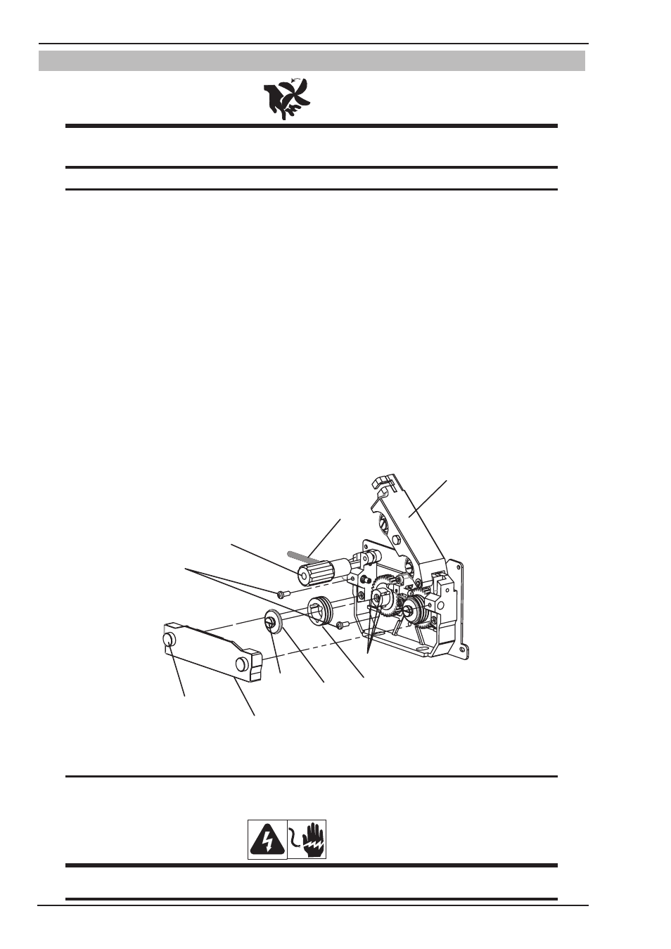
1. Loosen the Thumb Screw as shown in the figure below and remove the finger guard.
2. Swing the Pressure Adjusting Knob down and the Pressure Roll Arm automatically springs up.
3. Rotate the Screw counter-clockwise and remove the Screw, Washer and Feed Roll.
4. Make the three key slots on the Feed Roll align at the three Positioning Pins, and install the Feed Roll,
Washer and Screw.
5. Tighten the screw clockwise.
6. Lower the Pressure Roll Arm.
7. Swing the Pressure Adjusting Knob back into place.
8. Use the Pressure Adjusting Knobs to create a “snug” condition. (Clockwise to tighten and Counter Clockwise
to loosen). Secure the finger guard with the Set Screw and Thumb Screw.
9. To remove the inlet guide remove the M6 × 14 screw as shown in the figure below.
10. To remove the Euro torch adaptor remove the M6 × 14 screw as shown in the figure below.
Finger Guard
Thumb Screw
Screw
Washer
Feed Roll
Screw, M6 × 14
Inlet Guide
Pressure Roll Arm
Pressure Adjusting Knob
Art # A-11779
Positioning Pin
Figure 3-30 Changing Feed Roll (Right Side as Example)
NOTE
All grooved Feed Rolls have their wire size or range stamped on the side of the roll. On rolls with dif-
ferent size grooves, the outer (visible when installed) stamped wire size indicates the groove in use.
WARNING
The welding wire is electrically Hot if it is fed by depressing MIG Gun switch. Electrode contact to work
piece will cause an arc with MIG Gun switch depressed.