08 servicing machine torch (pcm) components, 08 servicing machine torch (pcm) components -9 – Tweco PCM-62 Machine Torch User Manual
Page 37
Manual 0-2817
5-9
SERVICE
D. Replacing Hand Torch Control Switch
1. Strip back the insulation from the Torch Switch
leads approximately 3/16". Install heat-shrink
insulation on the Torch Switch leads. Crimp butt
splices onto the two Torch Switch leads and onto
the switch leads in the Torch Leads assembly.
Slide the sheat-shrink insulator over the butt
splices. Use a heat gun to shrink the heat-shrink
insulation into position on the butt splices.
2. Position Torch Head and Torch Control Switch in
handle, making sure all connectors and leads do
not extend beyond the edge of the handle.
3. Position Pilot Lead under the Negative / Plasma
Lead.
4. Position the Pilot Lead so that the screw will not
penetrate the Insulation Sleeving when the handle
halves are reassembled.
NOTE
For safety reasons, it is critical that the sleeving
not be used if it is damaged during reassembly.
Replace sleeving if damaged.
5. Replace the handle and secure with five screws
as follows:
a. Insert the two screws at the Torch Head end
of the Handle and torque to 15 in-lbs.
b. Insert the two screws at the Torch Lead end of
the Handle and torque to 15 in-lbs.
c. Insert the center screw and torque to 15 in-lbs.
d. Check the Torch Trigger for proper operation.
It should move freely and not bind. If the trig-
ger binds, loosen the center screw only until
the Trigger moves freely.
A-02824
Handle Half
#1
#2
#3
Install Screws In
Sequence Shown
Figure 5-12 Torch Handle Screw Installation
5.08 Servicing Machine Torch (PCM)
Components
WARNINGS
Disconnect primary power to the system before
disassembling the torch or torch leads.
DO NOT touch any internal torch parts while the
AC indicator light of the Power Supply is ON.
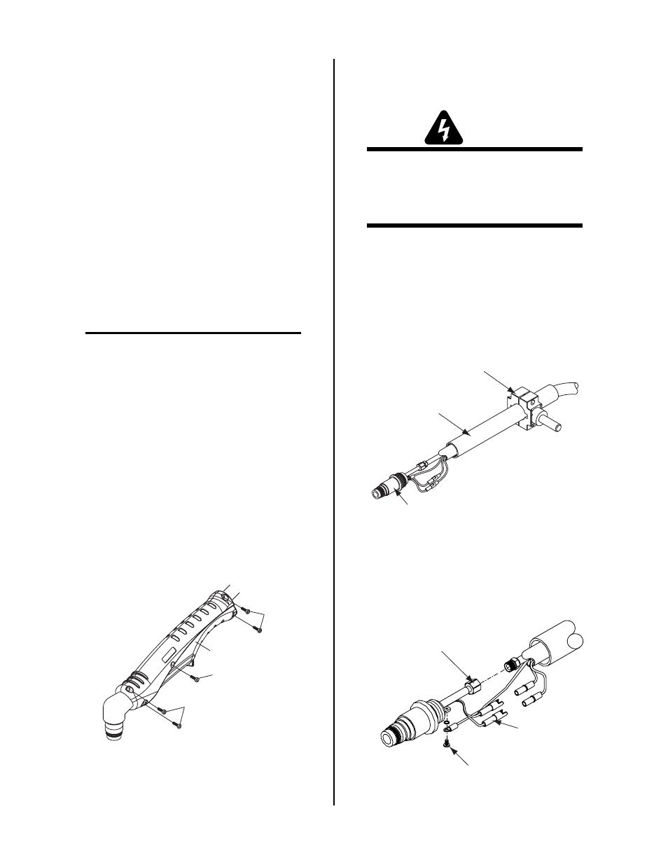
A. Removing Machine Torch Head
1. Unscrew the positioning tube from the Torch
Head.
2.
Slide the positioning tube back over the leads to
expose the Negative / Plasma Lead connection,
Pilot Lead connection, and two PIP (parts - in -
place circuit) connectors.
Positioning
Tube
Pinch Block
Assembly
Machine Torch Head
A-02592
Figure 5-13 Torch Mounting Assembly
4. Disconnect the Negative / Plasma and Pilot Leads
and the PIP connectors to allow removal of the
Torch Head Assembly.
Pilot Lead
Connection
Parts-in-Place
Wires
Negative/Plasma
Lead Connection
A-02581
Figure 5-14 Torch Head Removal