Tweco PCM-62 Machine Torch User Manual
Page 36
SERVICE
5-8
Manual 0-2817
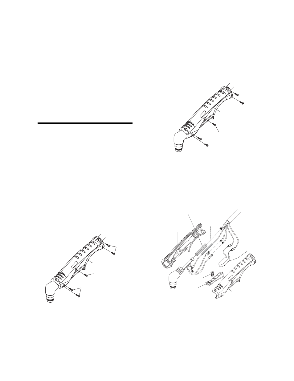
7. Place the Torch Head Assembly in the handle shell
halves keeping in mind the following:
• Place the torch head assembly switch leads so
that no connectors or wires extend beyond the
edge of the handle.
• Allow sufficient slack in the leads to avoid
pulling the leads tightly around the edge of
the handle.
• Position Pilot Lead under the Negative /
Plasma Lead.
• Position the Pilot Lead so that the screw will
not penetrate the Insulation Sleeving when the
handle halves are reassembled.
NOTE
For safety reasons, it is critical that the sleeving
not be used if it is damaged during reassembly.
Replace sleeving if damaged.
8. Place the torch handle halves together and install
the five assembly screws as follows:
a. Insert the two screws at the Torch Head end
of the Handle and torque to 15 in-lbs.
b. Insert the two screws at the Torch Lead end of
the Handle and torque to 15 in-lbs.
c. Insert the center screw and torque to 15 in-lbs.
d. Check the Torch Trigger for proper operation.
It should move freely and not bind. If the trig-
ger binds, loosen the center screw only until
the Trigger moves freely.
A-02824
Handle Half
#1
#2
#3
Install Screws In
Sequence Shown
Figure 5-9 Torch Handle Screw Installation
9. Install the front end torch parts.
C. Removing Hand Torch Control Switch
To remove the Torch Control Switch Assembly re-
quires gaining access to the switch wiring and re-
quires partial disassembly of the torch handle per the
following procedure:
1. Remove the five screws from the torch handle as-
sembly. Pull the halves apart and set aside.
A-02823
Handle Screws
(Five Places)
Handle Half
Figure 5-10 Torch Handle Screw Removal
2. Cut the Torch Switch leads between the butt
splices and the torch leads, and as close as pos-
sible to the splices.
Handle Shell
Handle Shell
Spring
Trigger
Torch
Switch
Negative / Plasma Lead
Insulation Sleeving
Pilot Lead
Insulation
Sleeving
A-03544
Figure 5-11 Hand Torch Assembly
3. Remove the defective Torch Switch from the
handle.