Section 2: introduction, 01 scope of manual, 02 general description – Tweco PCM-62 Machine Torch User Manual
Page 13: 03 specifications & design features, Section 2, Introduction -1
Manual 0-2817
2-1
INTRODUCTION
SECTION 2:
INTRODUCTION
2.01 Scope of Manual
This manual contains descriptions, operating instructions
and maintenance procedures for the PCH/M-62 Torch.
Service of this equipment is restricted to properly trained
personnel; unqualified personnel are strictly cautioned
against attempting repairs or adjustments not covered in
this manual, at the risk of voiding the Warranty.
Read this manual thoroughly. A complete understand-
ing of the characteristics and capabilities of this equip-
ment will assure the dependable operation for which it
was designed.
2.02 General Description
NOTE
Refer to Section 2.05, Introduction to Plasma, for
a more detailed description on plasma theory.
The Torch provides cutting capacity of up to 1/2 inch (12.7
mm) at 60 amperes drawn at the power supply.
In the torch, a single torch lead provides compressed air
from a single source to be used as both the plasma and
secondary gas. The air flow is divided inside the torch
head. Single - gas operation allows for a smaller sized
torch and inexpensive operation.
Plasma torches are similar in design to the common au-
tomotive spark plug. They consist of negative and posi-
tive sections which are separated by a center insulator.
Inside the torch, the pilot arc is initiated in the gap be-
tween the negatively charged electrode and the positively
charged tip. Once the pilot arc has ionized the plasma
gas, the superheated column of gas flows through the
small orifice in the torch tip, which is focused on the metal
to be cut.
2.03 Specifications & Design
Features
Refer to Appendix Pages for additional specifications as
related to the Power Supply used.
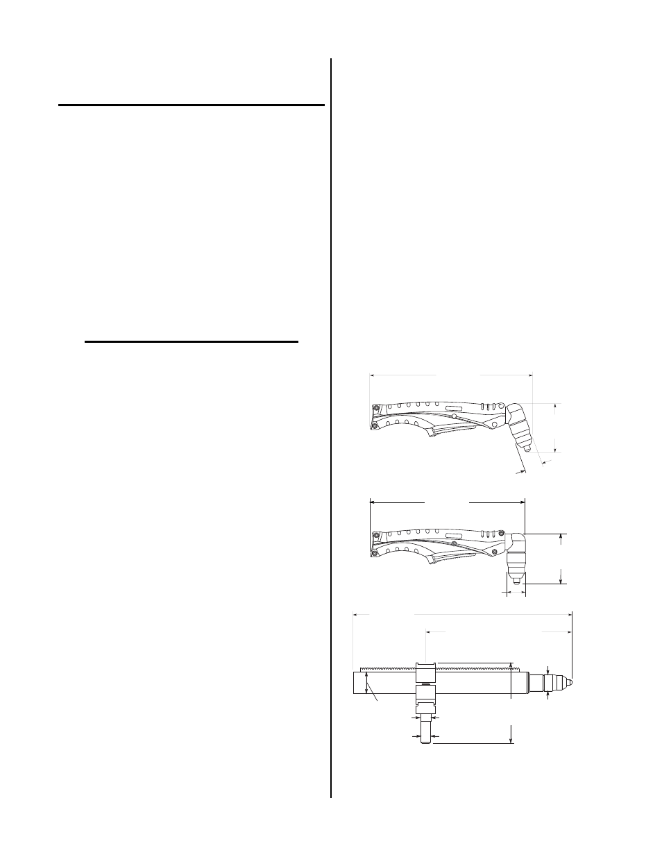
A. Torch Configurations and Dimensions
1. Hand Torch
Available with torch head at 70° and 90° to the
torch handle. The hand
torches include an ergo-
nomic torch handle and torch trigger assembly.
2. Machine Torch
The standard machine torch has a fiberglass posi-
tioning tube with rack & pinch block assembly.
Available options include a kit with metal mount-
ing tube with rack & pinion assembly or a kit with
the pinion assembly only.
3.0 in
(76.2 mm)
10.5 in
(267 mm)
A-02813
1.1in
(28 mm)
10.0 in
(254 mm)
3.4 in
(86.4 mm)
1.1in
(28 mm)
14.1 in
(358 mm)
0.6 in
(15.2 mm)
0.8 in
(20.3 mm)
5.1 in
(129.5 mm)
1.1 in
(28 mm)
1.4 in
(35.6 mm)
13.5 in (343 mm) Max
3.7 in (94 mm) Min
Figure 2-1 Torch Configurations and Dimensions