Tweco 1000 Merlin(Sept1999) User Manual
Page 31
Manual 0-2731
27
OPERATION
A-02173
3
2
1
4
5
6
7
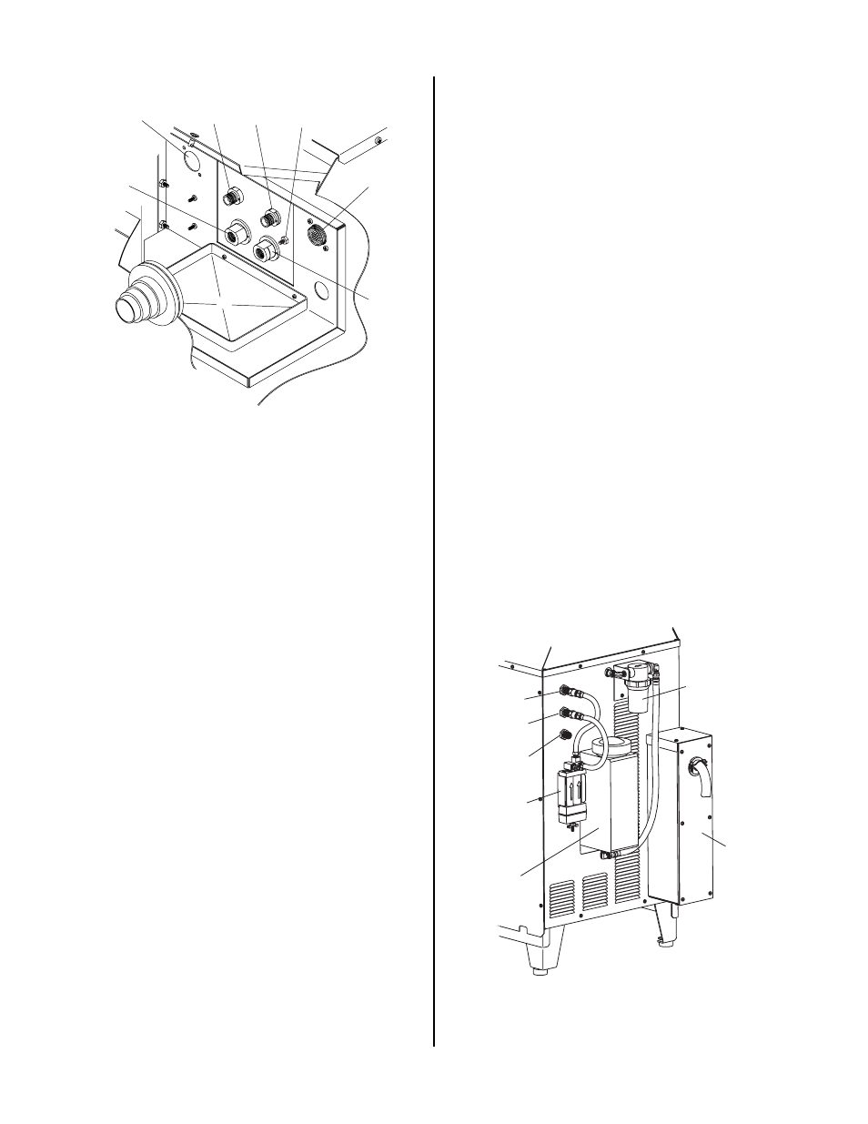
Figure 4-5 Torch Panel Connections
1. Control Cable Connector
Connects the Standoff Control (SC11), CNC or
Remote Hand Pendant controls for the system.
2. Plasma (+) Gas Lead Connection
Left-hand thread fiting to connect the torch plasma
lead to the unit.
3. Secondary Gas Lead Connection
Fitting to connect the torch secondary lead to the
unit.
4. Coolant Supply Lead Connection
Fitting to connects the torch coolant supply lead
to the unit.
5. Coolant Return (-) Lead Connection
Left-hand thread fitting to connect the torch cool-
ant return lead to the unit.
6. Torch Lead Shield Stud
Stud used to secure the torch lead shield ring lug
when system is used without the Optional Remote
Arc Starter.
7. Optional Remote Arc Starter Control Connector
Connector used only when the Optional Remote
Arc Starter is installed. Connection for the con-
trol cable between the Power Supply and the Re-
mote Arc Starter.
E. Rear Panel
1. PLASMA Gas Input Fitting
1/4" NPT female gas fitting used to supply the plasma
gas to the system.
2. SECONDARY Gas Input Fitting
1/4" NPT female gas fitting used to supply the sec-
ondary gas to the system.
3. SECONDARY WATER Fitting
1/4" NPT female fitting used for connection of tap
water to the Power Supply. The water can be used as
a secondary gas for the torch when the front panel
SECONDARY switch is in the WATER position.
4. Coolant Reservoir and Filler Cap
The coolant reservoir supplies the system with cool-
ant to cool the torch parts during operation. The maxi-
mum capacity of the reservoir is two gallons of cool-
ant.
Inside the reservoir, in the filler neck, is a basket and
a deionizer bag. The bag removes charged particles
from the coolant after it is returned to the reservoir
and prevents the coolant from becoming conductive.
If the coolant in the reservoir breaks down because of
these charged particles then the coolant must be re-
placed.
1
2
3
4
5
6
A-02353
7
Figure 4-6 Power Supply Rear Panel