Tweco 1000 Merlin(Sept1999) User Manual
Page 20
INSTALLATION PROCEDURES
16
Manual 0-2731
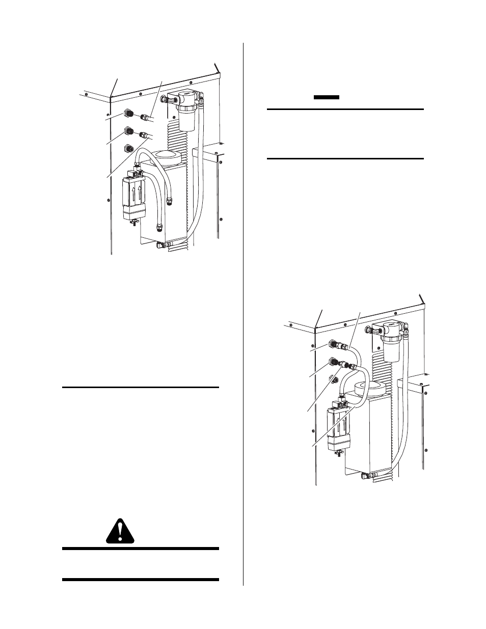
PLASMA GAS
Fitting
SECONDARY
GAS Fitting
Plasma Gas
Hose
Secondary Gas
Hose
A-02349
Figure 3-3 Gas Connections Using Gas Cylinders
c. Connect the gas supply hose from the second-
ary gas supply directly to the input fitting on
the rear panel of the Power Supply marked
SECONDARY.
C. Using Plasma Shop Air And Secondary
High-Pressure Gas Cylinder
NOTES
Refer to the regulator manufacturer’s specifications
for installation and maintenance procedures. Re-
fer to Section 6.05, System Options and Accesso-
ries, for a listing of available high-pressure regu-
lators.
Do not use an air line filter with high pressure gas
cylinders.
1. Examine the cylinder valves to be sure they are clean
and free of oil, grease or any foreign material. Mo-
mentarily open each cylinder valve to blow out any
dust which may be present.
WARNING
Do not stand in front of the valve outlet when open-
ing.
2. Each cylinder must be equipped with an adjustable
high-pressure regulator capable of pressures up to 125
psi (8.6 BAR) maximum and flows of up to 700 scfh
(328 lpm) for cutting or gouging.
CAUTION
Maximum input pressure to the internal regula-
tor on the Power Supply must not exceed 125 psi
(8.6 BAR).
NOTE
A typical 50 lb. CO2 cylinder can deliver a con-
tinuous flow rate of 35 scfh (16.5 lpm). To obtain
the required flow rate for the torch, it may be nec-
essary to manifold several CO2 cylinders. Con-
tinuous flow requirements will depend on the spe-
cific application and duty cycle.
3. Connect the gas supply to the Power Supply per
the following:
a. Remove the secondary gas hose and adapter
from the SECONDARY fitting at the rear panel.
PLASMA GAS
Fitting
SECONDARY
GAS Fitting
Plasma Gas
Hose
Secondary Gas
Hose
A-02356
Adapter Fitting
Figure 3-4 Removal Of Factory Installed Hardwre
b. Connect the gas supply hose from the second-
ary gas supply directly to the input fitting on
the rear panel of the Power Supply marked
SECONDARY.