07 work cable and ground connections – Tweco 1000 Merlin(Sept1999) User Manual
Page 22
INSTALLATION PROCEDURES
18
Manual 0-2731
NOTE
Equipment ordered as a system will have the Torch
factory connected to the Power Supply.
1. Turn the two latch screws securing the Control/Ac-
cess Panel to the power supply front panel.
Control/Access Panel
Latch Screw
Latch Screw
A-02165
Figure 3-7 Front Control/Access Panel
2. Lift up on the Control/Access Panel to gain access to
the torch bulkhead panel.
CAUTION
This system is designed for use with the Maximizer
300 Torch only. Do not connect any other torch to
this power supply.
3. Feed the end of the CNC/Remote Pendant Control
Cable, if used, through the rubber boot in the front
panel.
4. Connect the CNC/Remote Pendant Cable to Control
Cable Connector.
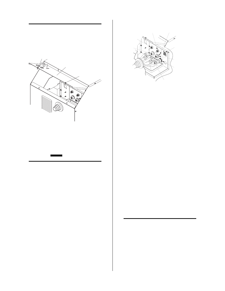
A-02271
Secondary
Gas
Plasma (+)
Gas
Control
Cable
Connector
Coolant
Return (-)
Coolant
Supply
Control
Cable
Connector
Torch Leads
Shield Stud
Ring Lug
(Shielded Torches Only)
Figure 3-8 Torch Leads Connections
5. Feed the end of the torch leads through the rubber
boot in the front panel.
6. Connect torch coolant and gas leads to the connectors,
as indicated on bulkhead.
7. Remove one nut and star washer fron the torch lead
shield stud.
8. Place the ring lug from the torch lead shield wire over
the stud and secure with the nut and star washer.
9. Close the access panel and turn the two latching screws.
3.07 Work Cable And Ground
Connections
A. Electromagnetic Interference (EMI)
Pilot arc initiation generates a certain amount of electro-
magnetic interference (EMI), commonly called RF noise.
This RF may interfere with other electronic equipment
such as CNC controllers, etc. To minimize RF interfer-
ence, follow these grounding procedures when install-
ing mechanized systems:
B. Creating an Earth Ground
NOTE
Refer to Appendix III for typical system ground-
ing diagram.
1. Install a ground wire (not included) between the sys-
tem and a solid earth ground (also called star ground).
To create a solid earth ground, drive a 1/2 in (12 mm)
diameter copper rod at least 6 - 8 ft (1.8 - 2.4 m) into
the earth so that the rod contacts moist soil over most
of its length. The required depth will vary depend-
ing on location (see NOTE). Locate the rod as close as