07 torch and leads troubleshooting, 07 torch and leads troubleshooting -6 – Tweco 1000 Cutting Systems User Manual
Page 38
SERVICE
5-6
Manual 0-2710
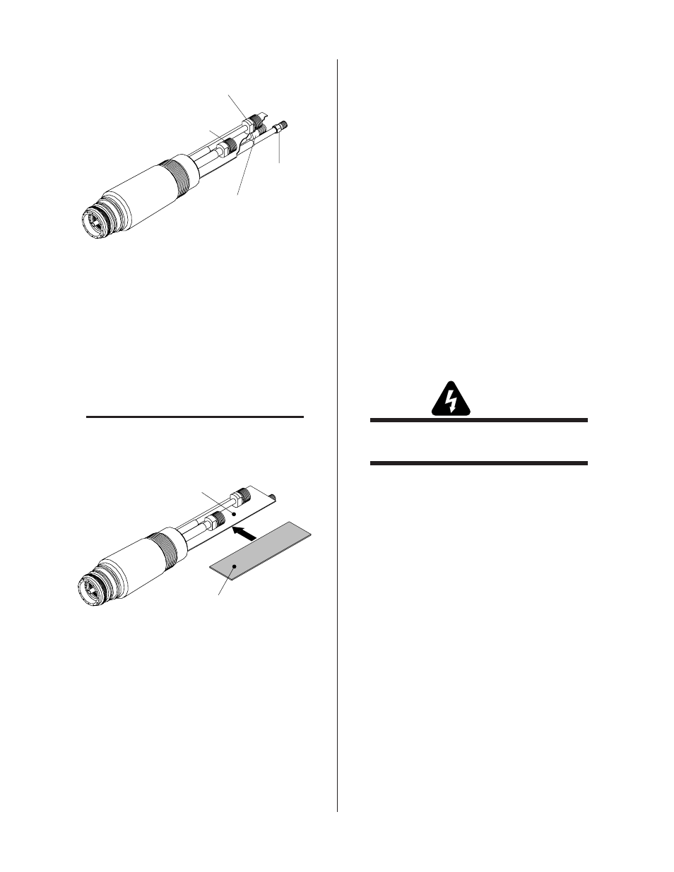
Plasma (+) Lead
Coolant Supply (-) Lead
(LH Threads)
Secondary
Lead
Coolant
Return Lead
A-02269
Figure 5-7 Torch Head Removal
B. Reassembling Torch Assembly
1. Remove the rigid insulator from the old Torch
Head Assembly from between the layers of
estermat paper.
2. Slide the rigid insulator between the layers of
estermat paper on the replacement Torch Head
Assembly (see note).
NOTE
Over a period of time there may be a breakdown of
the estermat paper causing the Torch Head to short
out if the rigid insulator is not installed.
Two Layers Of
Estermat Paper
Rigid Torch
Leads Insulator
A-01577
Figure 5-8 Rigid Insulator Installation
3. Secure the rigid insulator in place with electrical
tape.
4. Slide the replacement shrink-on tubing onto the
torch leads assembly.
5. Connect the plasma (+), secondary, coolant sup-
ply (-), and coolant return connectors.
6. Secure leads and tubing with single layer of elec-
trical tape.
7. Slide the torch adapter down over the leads and
screw the adaptor securely onto the back of the
torch head assembly.
8. Slide the positioning tube down over the leads
and thread it into the torch adaptor on the torch
head assembly.
9. Apply tape to the torch leads sleeving at the back
end of the positioning tube.
10. Position the shrink-on tubing over the taped area
and shrink into place.
11. Install the front end torch parts.
5.07 Torch And Leads
Troubleshooting
A. General Information
Failures in the Torch and Leads can be isolated to the Torch
Head or Torch Lead components. To properly isolate the
failed part requires the use of an ohmmeter and a Hi-Pot
Tester.
WARNING
The use of a Hi-Pot Tester should be performed only
by a qualified electronic technician.
In the Torch Head the center insulator separates the nega-
tive and positive charged sections of the torch. If the cen-
ter insulator does not provide adequate resistance, cur-
rent which is intended for the pilot arc may be dissipated
into the torch head, resulting in torch failure.
In the Torch Leads the negative and positive leads are
isolated from each other. If there is not adequate resis-
tance between the leads then torch failure may occur.
B. Quick Check Procedure
This quick check will identify major isolation failures in
the Torch Head or Torch Lead components using an ohm-
meter.
The actual assembly and consumables may vary for dif-
ferent torches but the basic procedure is the same for all
torches. Make the quick check on the Torch Head and
Leads as follows: