Tweco 1000 Cutting Systems User Manual
Page 21
Manual 0-2710
3-3
INSTALLATION
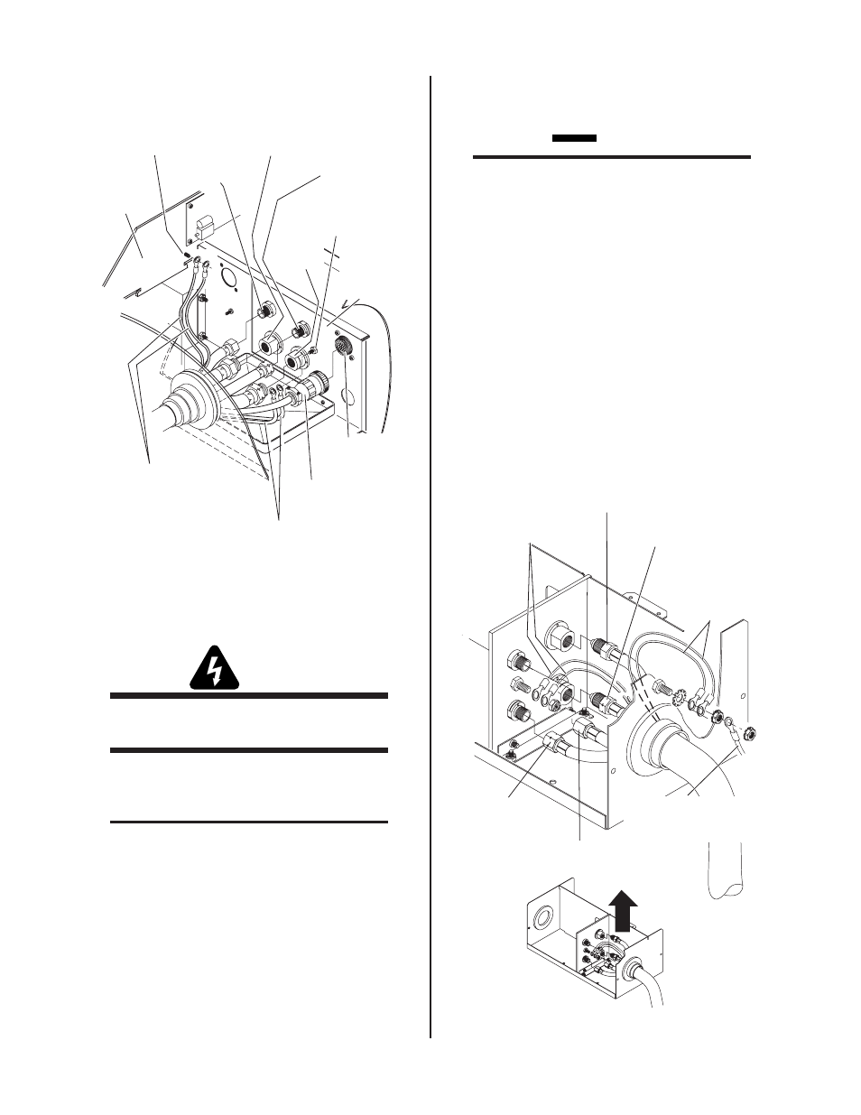
Secondary
Gas
Plasma (+)
Gas
Control Cable
Connector
Coolant
Supply (-)
CNC Control
Cable
RED Shield Wires
With Ring Lugs
Torch Leads
Shield Stud
(for INNER Shields)
GREEN / YELLOW Shield
Wires with Ring Lugs
Torch Leads
Shield Stud
(for OUTER Shields)
Coolant
Return
Art # A-03997
Power
Supply
Chassis
Torch
Bulkhead
Panel
Figure 3-3 Machine Torch Connections
B. Systems With Optional Remote Arc Starter
WARNING
Disconnect primary power at the source before dis-
assembling the torch or torch leads.
The Torch Leads connect directly to a bulkhead inside the
Remote Arc Starter. Connect the Torch Leads as follows:
NOTE
The Remote Arc Starter must be installed in the
system according to the Power supply Operating
Manual, 0-2708, supplied with the Power Supply.
1. Remove the cover from the Remote Arc Starter if
installed.
2. Remove the hardware attached to the ends of the
Torch Leads assembly with a wire tie.
3. Feed the torch leads through the boot on the torch
end of the Remote Arc Starter.
4. Connect the torch leads connectors to the bulk-
head connections per the following figure.
CAUTION
If the Arc Starter Box does not include a drilled hole
in the front panel as shown below for the outer
(GREEN / YELLOW) torch lead shields, perform
the following steps:
• Drill a hole in the area shown.
• Scrape both sides of the front panel down to bare
metal around the hole (to a diameter of ± 3/4" /
19 mm).
• Provide hardware as shown to secure the outer
(GREEN / YELLOW) torch shield leads to the
Arc Starter Box.
• Use the same hardware to connect a customer-
supplied external ground from the Arc Starter
Box to an earth ground.
Outer (GREEN /
YELLOW)
Torch Lead
Shields
External Ground
(Customer Supplied)
Art # A-04002
Torch Leads
Secondary Gas
Plasma Gas (+)
Left-Hand Thread
Coolant Supply (-)
Left-Hand Thread
Coolant
Return
Inner (RED) Torch
Lead Shields
Figure 3-4 Torch Leads Connections to Arc Starter Box