Cutmaster a40, a60 – Tweco A40-A60 CutMaster User Manual
Page 26
CUTMASTER A40, A60
INSTALLATION Manual 0-5120
3-2
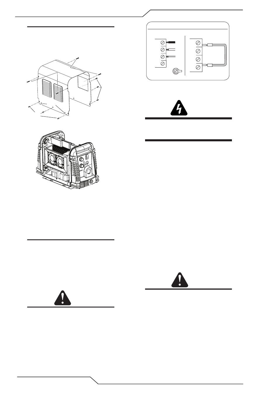
NOTE
The upper screws and lower screws are not the
same. Do not mix them. The upper screws are
for threading into the plastic of the front and
rear panels. DO NOT use the finer threaded
lower screws for this.
Upper
Screws
Lower
Screws
Lower
Screws
Art # A-08317
Slots
2. Carefully pull the Cover up and away from the
unit.
B. Cover Installation
1. Reverse previous procedures for cover instal-
lation.
NOTE
When installing the upper screws, attempt to re-
use the original threads. The easaiest way to do
this is by turning the screw counter-clockwise
until you feel the threads lign up, then begin to
turn the screw clockwise to tighten. Do not
over tighten.
C. Input Power Connections
CAUTION
Check your power source for correct voltage
before plugging in or connecting the unit. The
primary power source, fuse, and any extension
cords used must conform to local electrical code
and the recommended circuit protection and
wiring requirements as specified in Section 2.
All units are shipped from the factory with a
380/400Volt input power cable wired to the input
contactor in the three - phase configuration. The fol-
lowing illustration and directions are for replacing the
input power cable.
Art # A-08546
Three-Phase (3ø) and Jumper Settings
L1
L2
L3
L4
Jumper L1 -L4
L1
L2
L3
GND
L4
Three Phase Input Power Wiring
D. Connections to Three Phase Input Power
WARNING
Disconnect input power from the power sup-
ply and input cable before attempting this
procedure.
These instructions are for changing the input power
and or cable on the 208/230, 400, 460 VAC Power Sup-
ply to Three - Phase input power.
1. Remove the Power Supply cover per instruc-
tions found in this subsection A.
2. Disconnect the original input power cable
from the main input contactor and the chassis
ground connection.
3. Loosen the through - hole protector on the back
panel of the power supply. Pull the original
power cable out of the power supply.
4. Using a customer supplied four - conductor
input power cable for the voltage desired, strip
back the insulation on the individual wires.
5. Pass the cable being used through the access
opening in the back panel of the power supply.
Refer to Section 2 for power cable specifica-
tions.
CAUTION
The primary power source and power cable
must conform to local electrical code and the
recommended circuit protection and wiring
requirements (refer to table in Section 2).
6. Connect the wires as follows.
• Remove the copper bus bar jumper from
L2 and L3 on the contactor. See previous
illustration.
• Green / Yellow wire to Ground.
• Remaining wires to L1, L2 and L3 input. It
does not matter what order these wires are
attached. See the previous illustrations.