Installation, Preparation, Installation location – tekmar 654 Snow Melting Control Installation User Manual
Page 4: Rough-in wiring physical dimensions
©
2013 654_D
-
06/13
4
of
44
Preparation
Tools Required -----------------------------------------------------------------------------------------
-----------------------------------------------------------------------------------------
tekmar or jeweller screwdriver
Phillips head screwdriver
•
•
Needle-nose Pliers
Wire Stripper
•
•
Materials Required -------------------------------------------------------------------------------------
-------------------------------------------------------------------------------------
18 AWG LVT Solid Wire (Low Voltage Connections)
•
tekmar 24 V (ac) Transformer 009
•
Installation Location
When choosing the location for the control, consider the
following:
Interior Wall.
Keep dry. Avoid potential leakage onto the control.
Relative Humidity less than 90%. Non-condensing
environment.
No exposure to extreme temperatures beyond -4 to
122°F (-20 to 50°C).
No draft, direct sun, or other cause for inaccurate
temperature readings.
•
•
•
•
•
Away from equipment, appliances, or other sources of
electrical interference.
Easy access for wiring, viewing, and adjusting the display
screen.
Approximately 5 feet (1.5 m) off the finished floor.
The maximum length of wire is 500 feet (150 m).
Strip wire to 3/8" (10 mm) for all terminal connections.
Use standard 8 conductor, 18 AWG wire.
•
•
•
•
•
•
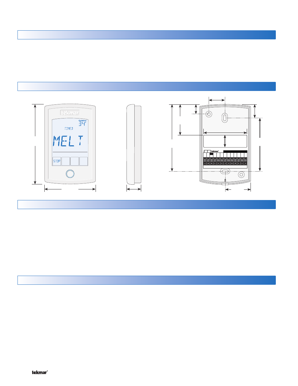
Rough-In Wiring
Physical Dimensions
Low Voltage Wiring
-------------------------------------------------------------------------------------
-------------------------------------------------------------------------------------
Each cable must be pulled from the equipment to the control’s
plastic enclosure. All low voltage wiring connections enter
the enclosure through the square knockout on the rear. It is
recommended to label each cable for easy identification. All
low voltage wires are to be stripped to a length of 3/8" (9 mm)
to ensure proper connection to the control.
Pull four conductor 18 AWG LVT cable, up to 500 feet
(150 m) for the following equipment:
Snow Sensor 095
Pull five conductor 18 AWG LVT cable, up to 500 feet
(150 m) for the following equipment:
Snow / Ice Sensor 090 or 094
•
•
Pull two conductor 18 AWG LVT cable, up to 500 feet
(150 m) for the following equipment:
24 V (ac) power from transformer
Outdoor temperature sensor
Supply sensor (if applicable)
On/off boiler (if applicable)
Modulating boiler 0-10 V (dc) or 4-20 mA (if applicable)
Mixing valve or mixing injection pump 0-10 V (dc) or 4-20
mA (if applicable)
Boiler return temperature sensor (if applicable)
Alert output (if applicable)
tekmarNet
®
4 communication to other devices
•
•
•
•
•
•
•
•
•
Front View
5"
(127 mm)
3-1/4"
(82 mm)
Side View
15/16"
(23 mm)
Mounting Base
654
Slab
Brn
+
Mod
tN4
Aux Ht
R
C
Bret
Out/
Com
Com
Blk
Yel Blu Red
Sup
No Power
1-1/2"
(38 mm)
9/16"
(14 mm)
CL
1-7/8"
(47 mm)
3/4"
(19 mm)
CL
CL
13/16"
(20 mm)
4"
(102 mm)
2-1/2"
(64 mm)
29/32"
(23 mm)
3-1/4"
(83 mm)
Installation