Wiring the outdoor sensor 070, Mounting the boiler and mix sensor 082 – tekmar 402 House Control Installation User Manual
Page 8
© 2010
D 402 - 09/10
8 of 32
Connect 18 AWG or similar wire to the two terminals
provided in the enclosure and run the wires from the
070 to the control. Do not run the wires parallel to tele-
phone or power cables. If the sensor wires are located
in an area with strong sources of electromagnetic in-
terference (EMI), shielded cable or twisted pair should
be used or the wires can be run in a grounded metal
conduit. If using shielded cable, the shield wire should
be connected to the Com or Com Sen terminal on the
control and not to earth ground.
Follow the sensor testing instructions in this brochure
and connect the wires to the control.
Replace the front cover of the sensor enclosure.
•
•
•
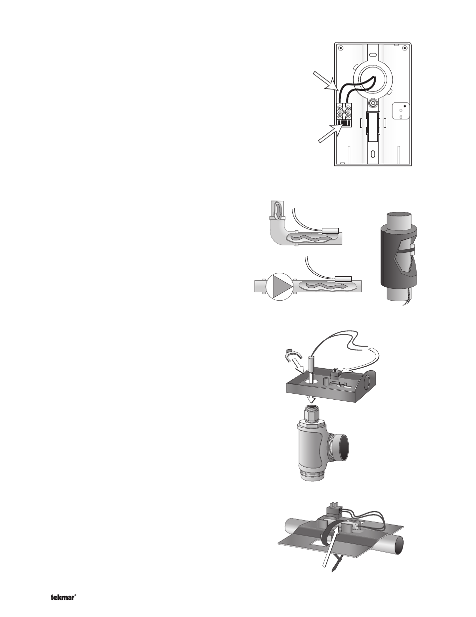
Wiring the Outdoor Sensor 070 -----------------------------------------------------------------------
-----------------------------------------------------------------------
Wires from outdoor
sensor to control
terminals
(Com Sen - Out Sen)
Sensor is built into
the enclosure
Mounting the Boiler and Mix Sensor 082 -------------------------------------------------------------
-------------------------------------------------------------
Note: These sensors are designed to mount on a pipe or
in a temperature immersion well.
The Universal Sensor should be placed downstream of a
pump or after an elbow or similar fitting. This is especially
important if large diameter pipes are used as the thermal
stratification within the pipe can result in erroneous sensor
readings. Proper sensor location requires that the fluid
is thoroughly mixed within the pipe before it reaches the
sensor.
Strapped to Pipe
The Universal Sensor can be strapped directly to the pipe
using the cable tie provided. Insulation should be placed
around the sensor to reduce the effect of air currents on
the sensor measurement.
Immersion Well
If a Universal Sensor is mounted onto 1” (25 mm) diameter
L type copper pipe, there is approximately an 8 second
delay between a sudden change in water temperature and
the time the sensor measures the temperature change.
This delay increases considerably when mild steel (black
iron) pipe is used. In general, it is recommended that
a temperature well be used for steel pipe of diameter
greater than 1-1/4” (32 mm). Temperature wells are also
recommended when large diameter pipes are used and
fluid stratification is present.
Conduit Connection
The Universal Sensor 082 and Universal Sensor Enclosure
080 (sold separately) are specifically designed to mount
onto a 3/8” (10 mm) ID temperature well that is supplied
with an end groove. To install the well, plumb a ‘T’ into the
pipe and fix the well into the ‘T’. The 080 enclosure has
a 7/8” (22 mm) back knockout that must be removed and
fitted over the temperature well. The 082 is then inserted
into the well and the retaining clip supplied with the
enclosure is snapped onto the well end groove. If the well
has a threaded end, the installer must supply a standard
threaded conduit retaining ring. The two wires from the
sensor are connected to the terminal block provided in the
enclosure. The other side of the terminal block is used to
connect wires from the control.
Bottom of
Enclosure 080
Universal
Sensor 082
Cable Tie
Sensor Well
Retaining Clip
Universal
Sensor 082