tekmar 402 House Control Installation User Manual
Page 4
© 2010
D 402 - 09/10
4 of 32
The control requires an external transformer. A tekmar
Transformer 009 (or 009K which includes a 4”x 4” electrical
box) can supply up to 40 VA, and includes an in-line fuse
to protect the transformer and control.
In order to correctly size the external transformer, all loads
connected to the control must be taken into account.
When adding up the loads, consider the following:
tekmarNet
®
2 Thermostats draw approximately 2 VA each.
Each zone valve must be sized for peak load. This can
be obtained by multiplying the peak current draw (in
Amps) by 24 V (ac).
•
•
If using a Floating Action mixing valve, add the VA
draw for the actuating motor. A tekmar Actuating Motor
741 draws 1.5 VA during normal operation.
The total power capacity of the power supply should be
larger than the total load of all the devices connected
to the control. This total load must not exceed 100 VA.
Multiple tekmar Transformer 009’s can be wired together
to increase total VA capacity.
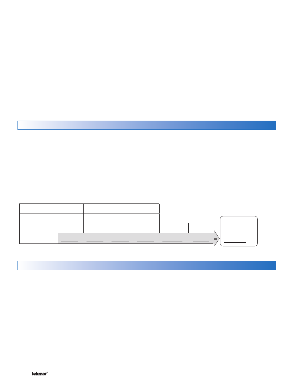
The following chart is provided to simplify transformer
sizing:
•
Zone
1
2
3
4
Thermostat Load
Zone Valve Load
Floating
Action (VA)
Control
Load (VA)
Total Zone Load
+
+
+
+
+
2
Transformer
must exceed:
VA
Sizing the Transformer
Control Wiring
Line Voltage Wiring-----------------------------------------------------------------------------------
-----------------------------------------------------------------------------------
Ground the Pumps
Connect the pump grounds to the power supply
ground as shown in Figure 1. The ground wire must
also be grounded to the electrical box.
Wire the Pump Neutrals
Connect the Neutral (N) wires from each pump and wire
to the 115 V (ac) Neutral (N) wire. If the transformer has
been mounted to this electrical box, connect its neutral
wire with this group. This is shown in Figure 2.
•
•
Wire the Pump Power (L)
Connect the 115 V (ac) line voltage (L) wire to the red
Pump Power (L) wire on the back of the House Control
and to the 115 V (ac) side of the transformer. Use a
wire nut or approved connector. See Figure 3.
Wire the Pumps
Wire each remaining line voltage pump wire into the
push-in wire connector of the corresponding pump
lead on the back of the House Control. This is shown
in Figure 4.
•
•
CAUTION: TURN ALL POWER OFF BEFORE PERFORMING ANY WIRING.
Each cable must be pulled from the equipment to the
control’s plastic enclosure. All low voltage wiring connections
enter the enclosure through conduit knockouts on the
sides, or through the square knockouts on the rear. It is
recommended to label each cable for easy identification.
All low voltage wires are to be stripped to a length of 3/8”
(9 mm) to ensure proper connection to the control.
Pull two conductor 18 AWG LVT cable, up to 500 feet
(150 m) for the following equipment:
tekmarNet
®
2 Thermostats
Zone Valves
Mixing Valve Actuator Proportional 0-10 V (dc)
Boiler Stage 1 T-T
•
•
•
•
Boiler Stage 2 T-T (if applicable)
Modulating Boiler 0-10 V (dc) or 4-20 mA (if applicable)
Outdoor Temperature Sensor
Boiler Supply Temperature Sensor
Mix Supply Temperature Sensor
DHW Tank Temperature Sensor (if applicable)
DHW Tank Aquastat (if applicable)
Setpoint Devices (if applicable)
Pull three conductor 18 AWG LVT cable for the following
equipment:
Mixing Valve Actuator Floating Action
tekmarNet
®
4 Accessories (User Switch, Timer)
•
•
•
•
•
•
•
•
•
•
Low Voltage Wiring -----------------------------------------------------------------------------------
-----------------------------------------------------------------------------------