Installation, Step one, Step two – tekmar 365 Mixing Control User Manual
Page 7: Step three, Setpoint operation
Copyright © D 365 - 06/00
7 of 16
Caution
Improper installation and operation of this control could result in damage to equipment and possibly even personal injury.
It is your responsibility to ensure that this control is safely installed according to all applicable codes and standards.
Step One
Getting ready
Check the contents of this package. If any of the contents listed are missing or damaged, please refer to the Limited Warranty and
Product Return Procedure on the back of this brochure and contact your wholesaler or tekmar sales agent for assistance.
Type 365 includes:
• One Control 365 • One Outdoor Sensor 070 • One Universal Sensor 071
• One Data Brochure D 365 • One Data Brochure D 001 • One Application Brochure A 365
• One Essay E 021
Other information available:
• Essay E 001 • Essay E 002
Read Brochure A 365 and E 021 and select the correct Application for your job.
Note:
Carefully read the details of the Application, and the Sequence of Operation sections in all applicable brochures to ensure that you
have chosen the proper control and understand its functions within the operational requirements of your system. Some applications
feature boiler return protection and require an additional Universal Sensor 071 to be ordered.
Step Two
Mounting of the base
The control should be removed from its base by pressing down on the release clip in the wiring chamber and sliding upwards on
the control. The base is then mounted in accordance with the instructions in the Data Brochure D 001.
Step Three
Rough-in Wiring
All electrical wiring terminates in the control base wiring chamber. It has standard 7/8" (22mm) knock-outs that will accept common
wiring hardware and conduit fittings. Before breaking out the knock-outs, check the wiring diagram and select those sections of
the chamber with common voltages, since the safety dividers will later prevent wiring from crossing between sections.
Power should not be applied to any of the wires during this rough-in wiring stage.
• Install the Outdoor Sensor 070, and the Universal Sensor 071 according to the instructions in the Data Brochure D 001 and
run the wiring back to the control.
Notes on operation of Minimum Return and Maximum Supply functions
At times, the control may be trying to control both the Maximum Supply and Minimum Return temperatures (e.g.. when leaving a
deep setback). When this occurs, the control is programmed to give priority to the Minimum Boiler Return function, and only the
"Min. Return" light will be displayed.
When the control is in WWSD, the "Min. Return" and "Max. Supply" lights will not be displayed.
When using a Return Sensor for Minimum Return protection, it is essential that there always be water flow past the return sensor
whenever there is a heat demand.
See Brochure A 365.
Caution:
The tekmar Mixing Control 365 is an operating control and not certified or intended for use as a primary safety device. Under
normal operating conditions, the control will provide excellent protection against excessive supply temperatures and low
boiler return temperatures; However, if fail-safe protection against either of these conditions is essential then separate
certified safety limit devices should be employed.
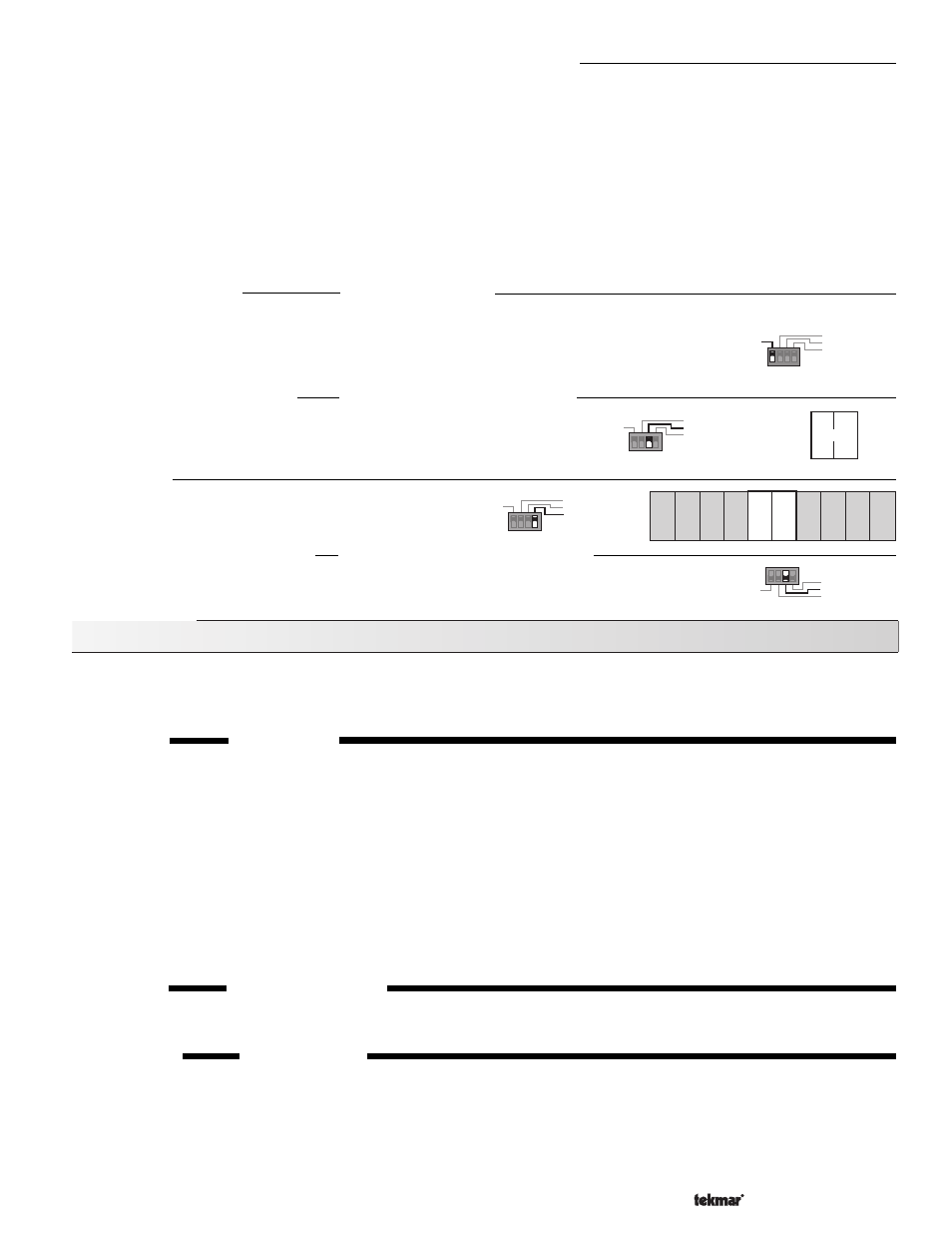
Selector Switch = External Heat Demand
Zone Control
Boiler on when 25% open
External Heat Demand
Setpoint
1
2
3
4
Dem Dem
Heat
1
2
Zone Control
Boiler on when 25% open
External Heat Demand
Setpoint
1
2
3
4
+
Setpoint Operation
When the control is in the Setpoint mode, it will control the supply water temperature based on the setting
of the Max./Setpoint dial. The Outdoor Sensor need not be installed and the Occupied, and Heating Curve
dials are inactive. If the control receives an Unoccupied signal, the supply temperature will be controlled
at the setting of the Unoccupied dial. When an optional Boiler Return Sensor 071 is installed, the Minimum
Boiler Return function is activated based on the setting of the "Min. Return" dial.
Selector Switch = Setpoint
Installation
External Heat Demand signal
A heat demand signal is caused by either 24 or 120Vac applied to terminals
Heat Dem — Heat Dem (1 and 2). This signal will activate the control, allowing
it to operate the system to deliver the selected setpoint temperature.
AND/OR
An active (calling for heat) 10 K Zone Control connected
to terminals
Com Sen — 10K Sen (14 and 15).
Reset
Permanent Heat Demand
Indoor Sensor
Boiler on when 10% open
1
2
3
4
Selector Switch = Permanent Heat Demand
12
13
2K
RTU
Com
Sen
16
Sup
Sen
17
Out
Sen
18
19
Com
–
Ret
Sen
11
10
+
4-20
UnO
Sw
14
Com
Sen
10K
Sen
15
Zone Control
Boiler on when 25% open
External Heat Demand
Setpoint
1
2
3
4
Permanent Heat Demand signal
A heat demand signal is continuously present and the control will continuously operate the system to
deliver the selected setpoint temperature.